Amplifying Analog Voltages with the LM358
05.03.2025
Elektronik | Funk | Software
Der Technik-Blog
05.03.2025

25.02.2025
25.02.2025
12.02.2025
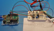
With the TTGO (LILYGO) GPS LoRa board you can build a very cheap and accurate LoRaWAN GPS tracker. The first part of the project "LoRa GPS Tracker" was about this board in general and about the setup of the UBLOX NEO6 GPS module. This article is about LoRa setup, registration in the LoRaWAN network and encoding and decoding of the payload.
The basic requirement is the installation of the ESP32 in the Arduino IDE. Furthermore the GPS receiver should be tested in advance as explained in the first part. For the startup of LoRa a library is needed. The library used is the Arduino LMIC LoRa Library from MCCI Catena. More information can be found on the website of the complete source code.
For the communication to the LoRaWAN network to work, the device must be registered in the network first. A general guide for registering ESP32 & Arduino boards with OTAA can be found here (German). Afterwards all keys, which are necessary for the respective LoRaWAN network, can be copied into the example code. An own LoRaWAN gateway is basically not necessary, but recommended. This way you contribute to the development of the LoRaWAN network and at the same time you have a very helpful tool for troubleshooting. An inexpensive and good multi-channel gateway would be the MikroTIK LR8 (German).
Before uploading the example code, some pins have to be adjusted for this. The GPS receiver communicates the position data serially to the ESP32. The necessary RX & TX pins are taken from the first part. The following lines define the pins for the GPS module:
#define SERIAL1_RX 34 // GPS_TX -> 34
#define SERIAL1_TX 12 // 12 -> GPS_RX
The communication between ESP32 and the LoRa module takes place via the SPI interface. While SPI pins on the Arduino have a fixed assignment, this is not the case on the ESP32. Different pins can be used for SPI. Therefore the SPI pins are defined in the setup method (void setup()). The following line defines the SPI pins for LoRa:
SPI.begin(5, 19, 27, 18);
Besides SPI, other pins are needed for the communication between ESP32 and LoRa chip. Very important is the reset pin and the DIO pins, especially the DIO0 pin. The following pin mapping must be declared before the methods:
const lmic_pinmap lmic_pins = {
  .nss = 18,
  .rxtx = LMIC_UNUSED_PIN,
  .rst = 23,
  .dio = {26, 33, 32},
};
Attention: There are different versions of the LILYGO TTGO board on the market. The pinout is different between the versions and may need to be adjusted
The "project_config" folder is located in the main directory of the MCCI library. In the "lmic_project_config.h" file, various options can be activated and deactivated. The frequency band is also set here. Another very useful option is the debug mode. By this activation (level 2) all information about the process will be displayed in the Serial Monitor. The following example configuration activates the EU band and the debug level:
// project-specific definitions
#define CFG_eu868 1
//#define CFG_us915 1
//#define CFG_au915 1
//#define CFG_as923 1
// #define LMIC_COUNTRY_CODE LMIC_COUNTRY_CODE_JP	/* for as923-JP */
//#define CFG_kr920 1
//#define CFG_in866 1
#define CFG_sx1276_radio 1
//#define LMIC_USE_INTERRUPTS

#define LMIC_DEBUG_LEVEL 2
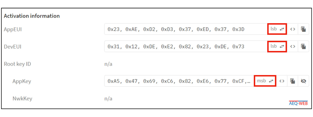
First, the keys for the LoRaWAN network must be adapted in the software. AppEUI and DevEUI are inserted into LSB. The AppKEY is copied 1:1 to MSB as shown in TTS.
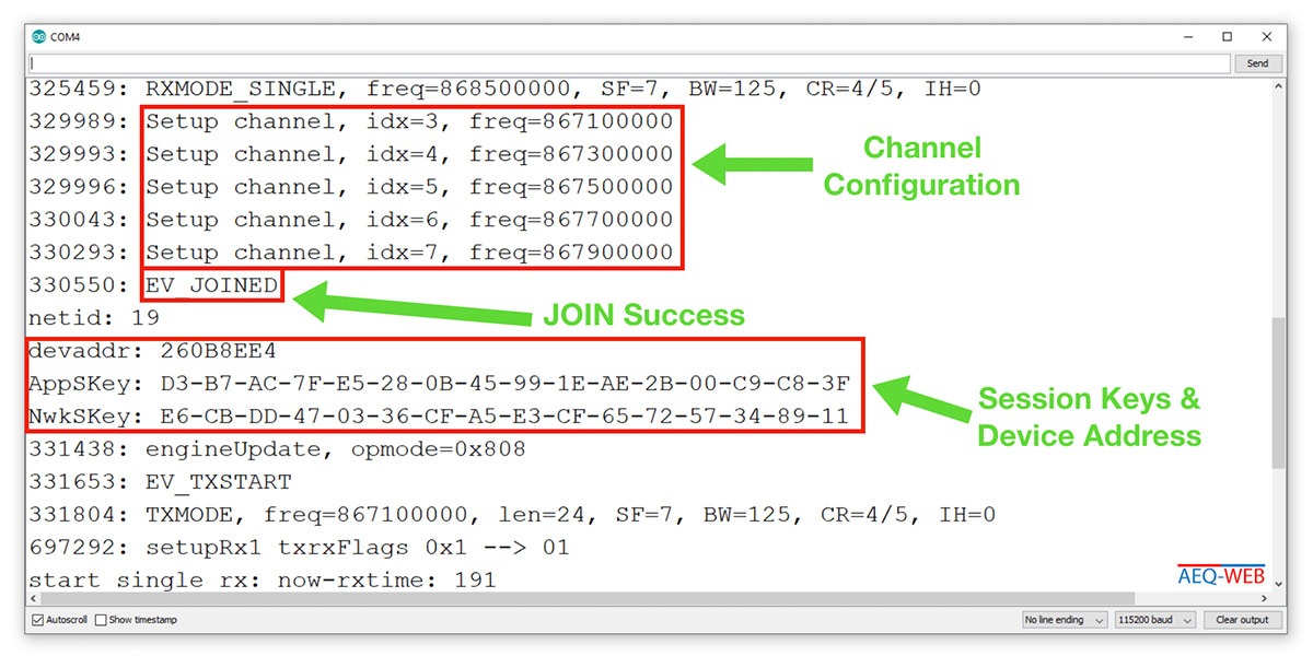
The software starts with a JOIN request and waits in the RX time windows for a response from the LoRaWAN network with the session keys. If the JOIN request from the LoRaWAN network was processed correctly, AppSKey (App Session Key) and NwkSKey (Network Session Key) should be displayed in the Serial Monitor. Afterwards the output "EV_Joined" is shown in the Serial Monitor. The JOIN request is now complete and a device ID has been assigned. The controller now has all the necessary data to be able to send future data sets to the LoRaWAN network. Only after the JOIN request was successful, the actual program starts to run in the main loop. The following screenshot shows the Serial Monitor after a successful JOIN at TTS:
The main program is constantly waiting for new NMEA data sets from the GPS module and fetches individual parameters from the data stream. Afterwards the received coordinates are converted into decimal degrees. A detailed description of the program flow and the conversion can be found in the first part.
Newly added is the method "generate_payload()". When calling this method, the parameters to be transferred (latitude, longitude, altitude & number of active satellites) are passed. In the method, the individual parameters are passed into the "uint8_t tx_payload[11]" array. The distribution of the payload looks as follows:
| From Bit | Until Bit | Description |
|---|---|---|
| 0 | 3 | Latitude (Long) |
| 4 | 7 | Longitude (Long) |
| 8 | 9 | Altitude (Integer) |
| 10 | 10 | Number of used sat (Byte) |
For a general detailed explanation of the LoRa payload and the encoder & decoder, check out the LoRa payload article and this YouTube video (German).
The TX interval is set to 60 seconds in the sample code and is only used for test purposes. In a busy network, however, this interval should definitely be increased so that capacities remain available for all participants. The payload is constantly regenerated and filled with current position data. Before the transmission, the hexadecimal payload is output in the serial monitor, as it will be seen later on the application server.
The decoder converts the payload generated by the GPS tracker back into its individual components. Previously separated varaiblen are merged again and partly also rounded. The payload decoder is copied as a JavaScript and can either be inserted globally in the application or only for the respective device. Afterwards, the coordinates should be displayed in plain text in the application in addition to the hexadecimal payload. The following decoder is inserted in the TTS application:
function Decoder(bytes, port) {
  var lat_coord = bytes[0] << 24 | bytes[1] << 16 | bytes[2] << 8 | bytes[3];
  var lat = lat_coord / 1000000 - 90;

  var lon_coord = bytes[4] << 24 | bytes[5] << 16 | bytes[6] << 8 | bytes[7];
  var lon = lon_coord / 1000000 - 180;

  var alt = (bytes[8] << 8 | bytes[9]);

  var sats = bytes[10];

    return {
      latitude:  Math.round(lat*1000000)/1000000,
      longitude:  Math.round(lon*1000000)/1000000,
      altitude: alt,
      sat: sats
    }
}
After inserting the decoder, the individual position parameters should be displayed with the next incoming data set:
In general, the LoRaWAN network does not store any data. Received data sets are forwarded from the Thing Network to software set by the user. For this purpose, there are already many providers, some of them even free of charge, that have a direct interface to the respective Thing Network and accept the data sets from the LoRaWAN network. Both TTN and TTS can forward the data to their own website via JSON post. Instructions on how to do this can be found in the third part.

Each LoRaWAN end device has its own device address, which is either statically assigned (ABP) or assigned by the LoRaWAN network (OTTA)
read more
The LoRaWAN FRM payload includes numerous headers, the encrypted payload, and an integrity code. This article explains the structure of an uplink message
read more
05.03.2025
25.02.2025
25.02.2025
12.02.2025
AEQ-WEB ist ein Blog von Alex & Andi, der sich mit Elektronik, Funk & Software beschäftigt
read moreAEQ-WEB © 2015-2026 All Right Reserved