Amplifying Analog Voltages with the LM358
05.03.2025
Elektronik | Funk | Software
Der Technik-Blog
05.03.2025

25.02.2025
25.02.2025
12.02.2025

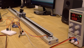
In the last post we wrote about the mechanical structure of our camera slider. In this article we continue with the construction manual for the electrical part.
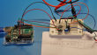
The stepper motor can not be connected to the microcontroller without additional electronics. Between the microcontroller and the motor we have a motor driver. The driver is a finished module, with a chip and four LEDs on the PCB. Four wires from the Arduino board provide control signals to the ULN2003 (IC type), which in turn amplifies the signals with its own power supply and supplies them to the motor. The rotating field that the stepper motor requires is already generated from your Arduino or microcontroller.

As controller, you can basically take any microcontroller that has at least four I/O pins. Because of the simplicity, we decided to choose an Arduino, because there is already an integrated library and you can do it with a little bit of code. The engine would also work with a STM Nucelo, Raspberry or NodeMCU.
The end position sensor is needed to find the zero point at powering the slider. From this zero point, the slider can start and the software is always aware of the slider position and how far he is from the starting point or end point. The code is programmed to always rotate to the sensor at startup or after a reset from the Arduino. If the microswitch triggers, the software knows where the slider is and moves away from the switch or end position sensor. This switch hangs on a pull-up circuit and is a normally closed contact. If it is pressed, the Arduino receives a low, otherwise it is always a high level. This will make it easier to detect a cable break or defective sensor.
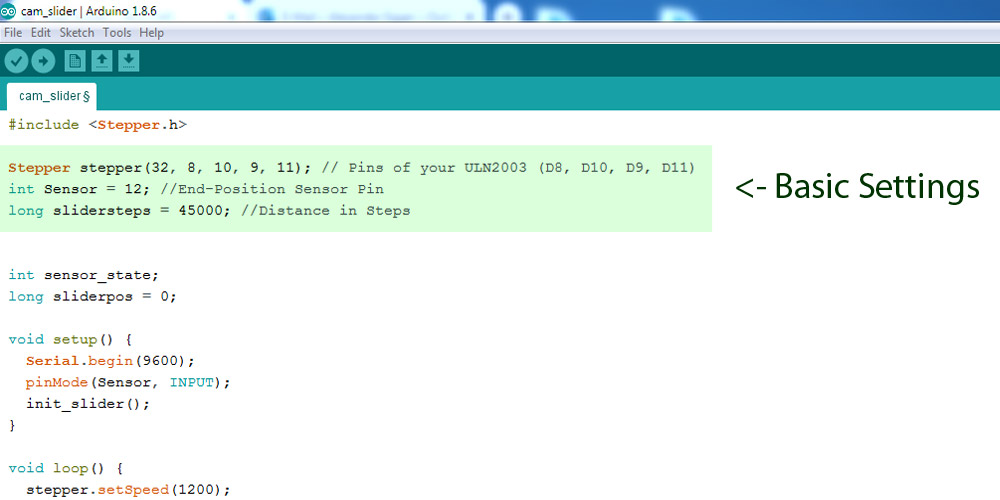
For the slider to work properly, the software needs to know the length of the route where the carriage is moving. For a certain distance (number of engine turns), which the slider should drive, you have a certain number of steps. Depending on the type of motor, a step may e.g. be a half, quarter or even full turn. In our construction, the actual length of the carriage is about 96 cm. These 96 cm correspond to our engine exactly 45000 steps. To determine the number of steps, you must move the slider towards the end position sensor. With the example code (stepper_test.ino) the motor can be controlled manually via the serial monitor. If the slider has been moved to the end position sensor and the sensor is activated, you can start driving the slider back to the other end. For this, all steps that the motor drives to the end must be recorded and then added. The sum of all steps required by the slider from the sensor to the other end is the number of steps for the entire length.
The software is programmed to automatically move the slider to the position sensor. In the Init-loop, the motor always drives -70 steps, and checks the status of the sensor. As soon as the slider triggers the sensor (low-level input), the init-loop is ended and the main program starts. In the main program, the slide always runs from end to end and once fast (2000) and once slow (200).
The camera slider should be so transportable as possible. Therefore, we have mounted two plastic boxes on the bottom side. The first box, which is located directly below the stepper motor, contains a self-made small shield with the pull-up circuit and the stepper controller. Together with the Arduino all the components are installed in this box. The two ALU square tubes contain the cables of the power supply and the sensor. In the second box, which is located under the return pulley, the batteries and a switch for the power supply can be accommodated.
Basically, this camera slider only drives at two speeds from A to B. Often you would like to define the speed and direction. This could be done locally and analogously via a potentiometer. Another possibility would be a control via Bluetooth or WiFi. You can either integrate appropriate modules or replace the Arduino with an ESP or a NodeMCU board.
The ZIP folder contains the example code and the stepper test code for determining the length to be approached in steps.
| Required components |
|---|
| 4,7 K Resistor |
| 28BYJ-48 Stepper |
| ULN2003 Controller |
| Microswitch |
| 2x 100x68x50 E-Box |
| Arduino Uno |

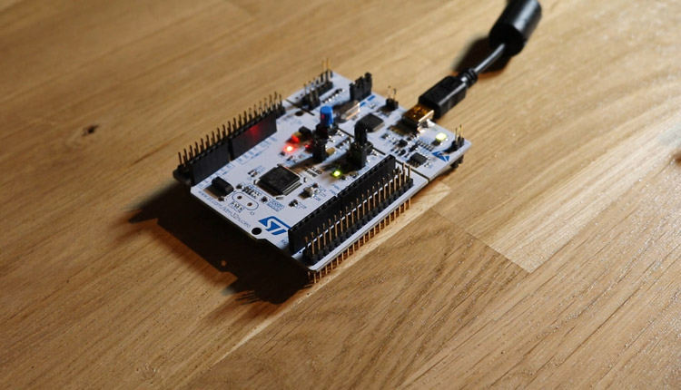
This article is a short instruction how to install the CubeIDE from STM. After install, we create a simple blink example with the onboard led in c
read more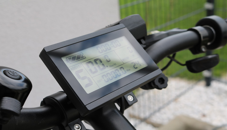
In this article we show how a conventional bike is converted into an electric bike and what hardware is needed for it.
read more
05.03.2025
25.02.2025
25.02.2025
12.02.2025
AEQ-WEB ist ein Blog von Alex & Andi, der sich mit Elektronik, Funk & Software beschäftigt
read moreAEQ-WEB © 2015-2026 All Right Reserved