Amplifying Analog Voltages with the LM358
05.03.2025
Elektronik | Funk | Software
Der Technik-Blog

05.03.2025

25.02.2025
25.02.2025
12.02.2025
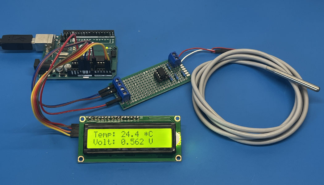
The PT100 is a temperature sensor with a positive temperature coefficient (PTC), predominantly used in industrial measurement technology. The sensor has a resistance of exactly 100 ohms at 0°C. As the temperature rises, the resistance value of the PT100 increases approximately linearly. The data evaluation with a microcontroller is problematic because the resistance value changes only slightly with a change in temperature, and this cannot be easily read using a simple voltage divider. This article discusses the construction of a very simple measurement amplifier for reading PT100 temperature sensors with Arduino.
Note: This circuit is a highly simplified measurement amplifier that allows temperature measurement with a PT100 sensor on Arduino. The line resistance is not considered, so adjustment with the sample code and a potentiometer is required.
The PT100 comes from the industrial technology sector and can measure very small temperature changes (0.1 degrees Celsius or better). However, this resolution is achieved only if the electronics for evaluation work with corresponding precision. According to the characteristic curve, the resistance value of a typical PT100 changes by about 0.39 ohms per 1°C. It is not uncommon for a long measurement line to the sensor to have a self-resistance of 0.5 to 1 ohm. Therefore, it may happen that due to the measurement line, the measured temperature is already one degree Celsius too high. To compensate for this, a three- or four-wire system is used. The evaluation of the sensor with a microcontroller is also problematic because the resistance of the PT100 changes only very slightly, and this cannot be evaluated with a simple voltage divider. Additionally, the resolution of analog inputs in many microcontrollers is often only 10 bits, making it practically impossible to measure small voltage changes. Lastly, it should be mentioned that the measuring current flowing through the PT100 should be chosen very small to prevent self-heating as much as possible.
The resistance of the PT100 changes with temperature. In order to measure this change with a microcontroller, the resistance must be converted into a voltage. If a PT100 and a 10K (0.1% tolerance) resistor are connected in series to a voltage source, a voltage can be measured in the middle that changes depending on the temperature:
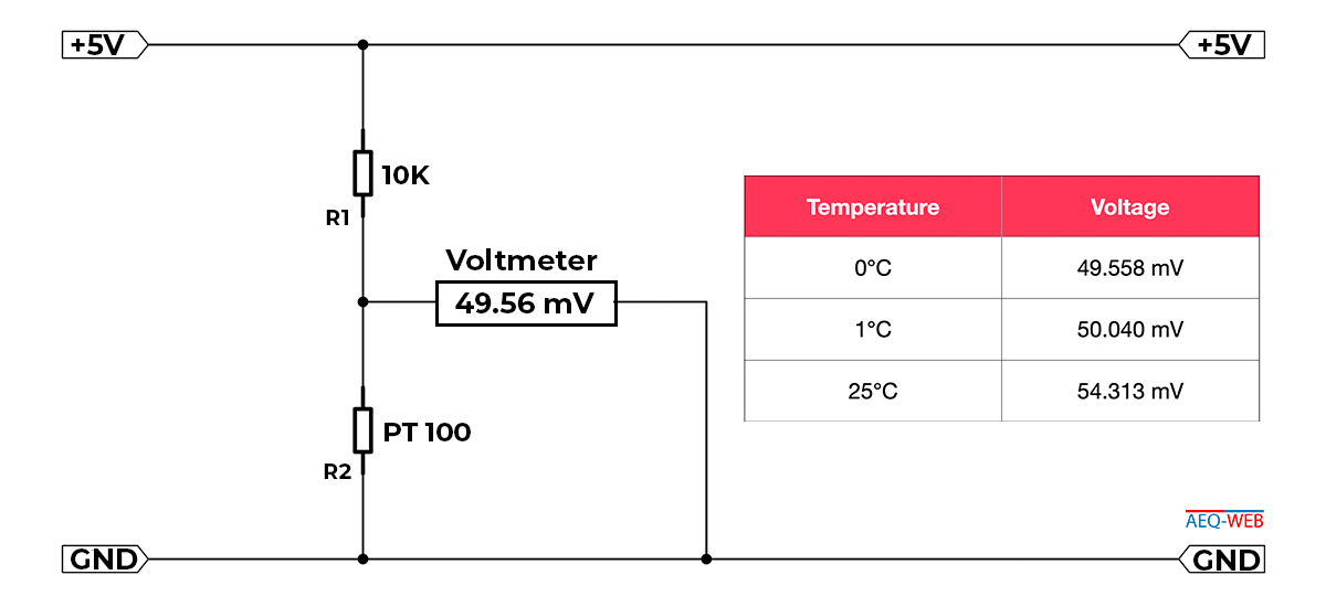
Looking at the table, it can be seen that the voltage changes by only about 4.75 mV with a temperature change of 25°C. A microcontroller such as the Arduino Uno can resolve the analog input with 10 bits (0-1023). With this, voltage measurement from 0 to 5 volts is possible in steps of 4.88 mV (5000 mV/1023 = 4.88 mV). Consequently, this means that the Arduino can only measure the temperature of the PT100 in approximately 25°C steps via the voltage divider, making this type of circuit unusable. The task now is to amplify the voltage change so that the Arduino can read the PT100 in 0.5°C steps with its 10-bit resolution.
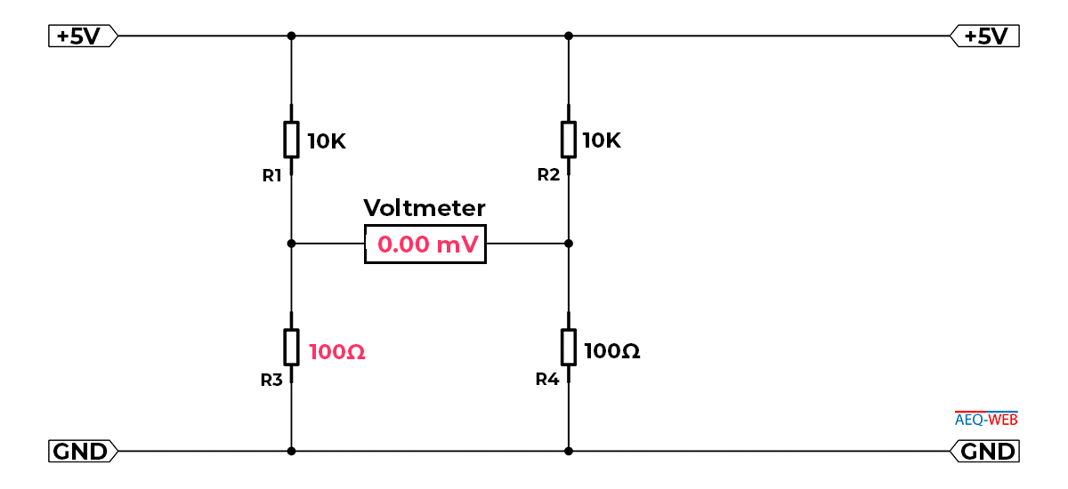
The Wheatstone Bridge is a circuit setup with four resistors. This allows very small resistance changes to be measured. Essentially, this circuit consists of two voltage dividers (R1, R3 and R2, R4). A multimeter is connected in the middle. If the resistance values of R1 and R3 are identical to R2 and R4, the voltage between the two dividers in the middle is zero:
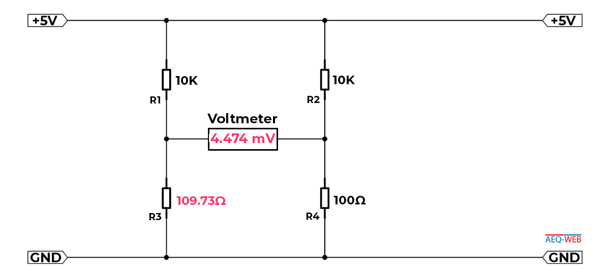
If the resistance R3 is replaced by the PT100, it has a resistance of 109.73 ohms at 25°C. This creates an imbalance in the bridge, causing the voltage between the dividers to rise:
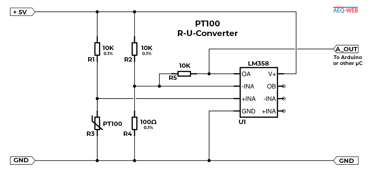
Now, instead of the multimeter, an operational amplifier is connected, which compares and amplifies the resulting voltage difference.
The LM358 is a simple operational amplifier which, in the following circuit, compares the voltage between the dividers of the Wheatstone Bridge and outputs the difference as voltage. The resistor R5 is located between the output and the inverting input and forms a feedback loop. This sets the amplification factor of the operational amplifier.
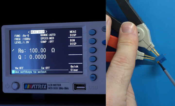
The finished circuit must now be calibrated once. For this purpose, a potentiometer or preferably a trimmer with ideally 200 ohms is used. With a multimeter, the trimmer is first set to exactly 100 ohms, and then the output voltage of the circuit is measured. A voltage of 0.079 volts was measured in the setup. Now it can be noted that a temperature of 0°C corresponds to a voltage of 0.0079 volts. Subsequent measurements are made at 25°C, 50°C, 100°C, and 150°C. The potentiometer or trimmer is adjusted according to the following table:
| Temp. | Ω | Voltage |
|---|---|---|
| 0°C | 100 | 0.079 |
| 25°C | 109.73 | 0.560 |
| 50°C | 119.40 | 1.040 |
| 100°C | 138.51 | 1.990 |
| 150°C | 157.91 | 2.950 |
*The values for the output voltage come from the setup with an operating voltage of 5.0 volts and may vary. Therefore, they are only to be understood as example values!
Observing the output voltages at different input resistances, it is noted that the ratio between resistance and voltage is not linear. In the example code provided by Arduino, this error is partially compensated for in software.
The complete example code can be copied from this page. The offset is set to 0°C and should be adjusted to the line resistance. The determined calibration values are inserted at the following location:
// Define known points (voltage & temperature)
const float voltages[] = { 0.079, 0.56, 1.04, 1.99, 2.95 };    // Voltages in Volts
const float temperatures[] = { 0, 25.0, 50.0, 100.0, 150.0 };  // Temperatures in Celsius
The software converts the input voltage from pin A0 into a temperature value. Based on the calibration values, the program selects the next higher voltage in the "voltages" array with the associated temperature value and calculates interpolation between the previous value in the array. The array can be supplemented with further data to resolve a specific measurement range even more precisely.
To achieve even more precise temperature resolution, a different microcontroller with a 12-bit resolution or an external ADC with a 16-bit resolution can be used. Lastly, it should be mentioned that the over 50-year-old LM358, while very popular and simple, could be replaced by better operational amplifiers. The second free input of the LM358 could possibly be used for measuring the line resistance to automatically compensate for it with the software.

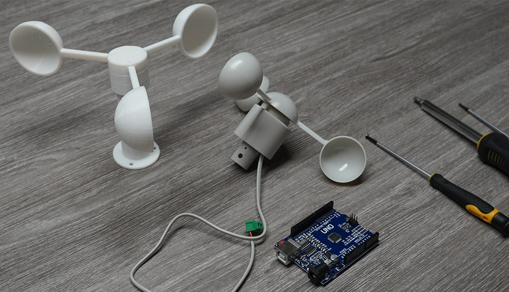
With a microcontroller like the Arduino, a small circuit and appropriate software the wind speed can be measured with an anemometer
read more
The PT100 is a very precise industrial temperature sensor. This article is about building a measuring amplifier for reading a PT100 on the Arduino
read more
05.03.2025
25.02.2025
25.02.2025
12.02.2025
AEQ-WEB ist ein Blog von Alex & Andi, der sich mit Elektronik, Funk & Software beschäftigt
read moreAEQ-WEB © 2015-2026 All Right Reserved