Amplifying Analog Voltages with the LM358
05.03.2025
Elektronik | Funk | Software
Der Technik-Blog
05.03.2025

25.02.2025
25.02.2025

12.02.2025
The PT1000 is an analog temperature resistor which is mainly used in industrial technology and for precision measurements. In order for the PT1000 to provide very accurate measurement values, this requires a very sensitive transducer that keeps the measurement current low and, if necessary, also takes line resistances into consideration. This article is about measuring temperature with a PT1000 via an operational amplifier and an Arduino Uno. Note: This project is just a simple example of a temperature measurement with the PT1000. Therefore, this circuit is not suitable for a precision measurement.
The PT1000 is a PTC resistor. This in turn means that the internal resistance increases with increasing temperature. PT100/PT1000 are very popular in industry because these temperature sensors provide very accurate measurement results, have a long life and can also be replaced very easy. Another advantage of these sensors is their linearity. This means that the output voltage of the transducer circuit behaves quite linearly throughout and can be processed by the microcontroller without complex mathematical formulas.
The primary difference between the two types is the internal resistance. The PT100 has exactly 100 ohms at 0 degrees Celsius, while the PT1000 has exactly 1000 ohms at 0 degrees Celsius. Although both sensors are quite accurate, there are some differences and also criteria by which the appropriate type is chosen.
PT100
The calculation of a PT100 is more complex than that of a PT1000, because the resistance only changes by a factor of 1/10 compared to the PT1000. For the evaluation unit, this means that the voltage difference is much smaller. Disturbing influences such as the line resistance or the measuring current passing through the PT100 have a much more massive effect as with the PT1000. Nevertheless, there are reasons why the PT100 is used, such as the larger measuring range. If temperatures of more than 200 degrees Celsius occur in the measuring range, the PT100 is definitely the better choice, since mostly the temperature with a resolution of one degree is sufficient even in such large measuring ranges.
PT1000
The PT1000 has a much higher resolution than the PT100. At 20 degrees Celsius, this sensor already has a resistance of almost 1078 ohms. Compared to the PT100, this would only have 107.8 ohms, which would only make a difference of 7 ohms at 20 degrees Celsius. With a simple voltage divider and a R2 of 10 kiloohm, one could already recognize the temperature change at the second decimal place at 5 volt voltage, which would not be possible with a PT100 without amplification. In addition, also due to the higher internal resistance, the measuring current is much lower and the line resistance through the test leads is less disturbing.
In general, the PT1000 is more suitable than the PT100 for small measuring ranges (-40 to +200 °C).
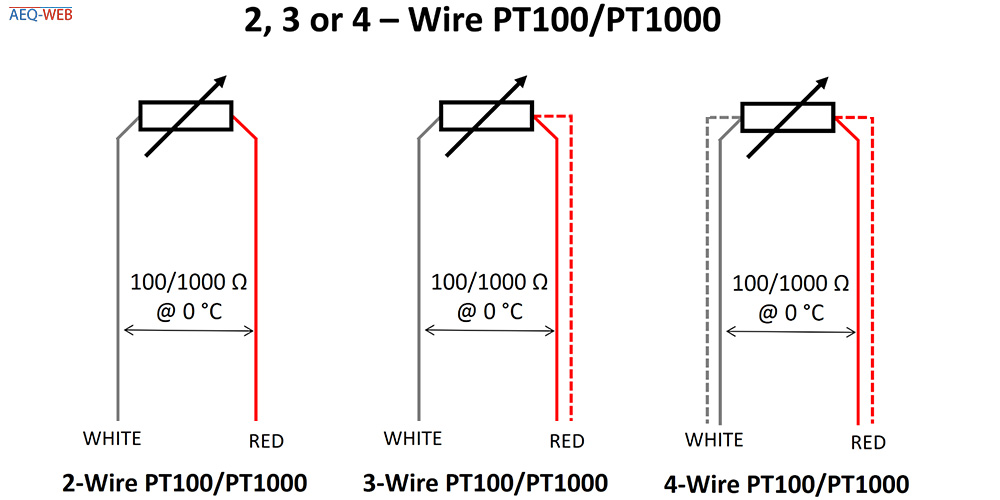
On the market there are different sensors with 2 to 4 wires. The simplest and cheapest version is the 2-wire version. In this version, the measuring resistor is located in a housing and is led out over the two connection lines. Especially with the PT100, the line resistance plays a major role. If the sensor is replaced or the cable is lengthened or shortened, the line resistance also changes. This in turn can lead to an incorrect measured value. In order to exclude measuring errors due to the line resistance, a 3- or 4-wire version was developed. In this circuit, depending on the type, one or both lines are led in parallel to the resistor. In the evaluation unit, there is then an additional measuring unit which determines the line resistance to the sensor and incorporates this accordingly into the correction. With the 3-wire version, one line is measured and with the 4-wire version, both line resistances are measured.
It is known that the resistance changes depending on the temperature. However, since you cannot measure resistance with a microcontroller, but only analog voltages, a corresponding converter is needed. The simplest converter is a classic voltage divider. For this, a resistor with a fixed known value is connected in series to the PT1000. In the middle of the two resistors the voltage can be measured, which changes depending on the temperature at the PT1000. Since the PT1000 itself could heat up due to a too high current, the second resistor must be correspondingly high. 10 kiloohm is a good compromise between voltage and current for this application. In addition, with a 10 kiloohm resistor in series to the PT1000 at 0 degrees Celsius, you have about 1/10 of the operating voltage as measuring voltage.
An example: The operating voltage of the voltage divider is 5.0 volts. The temperature at this time is exactly 0 degrees Celsius (1000 ohms at the PT1000). In the middle of the voltage divider a voltage of about 0.450 volts is applied. If the temperature rises to 20 degrees Celsius (about 1080 ohms at the PT1000), the output voltage from the voltage divider also rises to about 0.490 volts. As can already be seen from the example, the voltage difference is not very large, which leads to considerable problems on the Arduino with a resolution of 10-BIT.
Since the voltage change for the A/D converter in the Arduino is too small for a usable resolution, a corresponding amplifier is needed which is linear to input voltage. The following schematic shows a corresponding transducer with an LM358 op-amp.
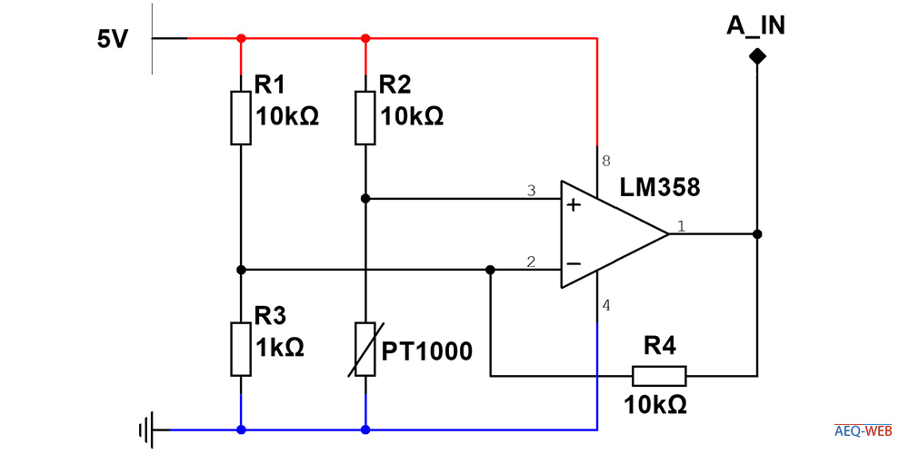
The whole circuit is powered by the 5V pin from the Arduino. The first two resistors (R1,R3) form the reference voltage of about 0.45 volts and are connected to pin 2 from the LM358. Assuming the current temperature at the PT1000 is 0 degrees Celsius, the second voltage divider (R2, PT1000) would also provide a voltage of about 0.45 volts at pin 3. The LM358 now compares both voltages and passes the voltage difference to the Arduino via pin 1. If the temperature at the PT1000 increases, the output voltage from the LM358 also increases significantly. Using this circuit you can now achieve a much higher voltage change depending on the temperature than with just a simple voltage divider. Thus the Arduino is now able to process the temperature in a higher resolution. The measuring range can be adjusted via the resistors R2 & R4. If you change the resistor R4, the output voltage at the LM358 changes as well. By the way, this method is called ratiometric measurement.
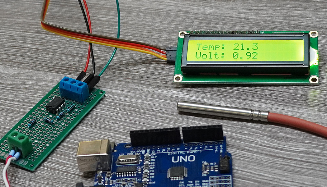
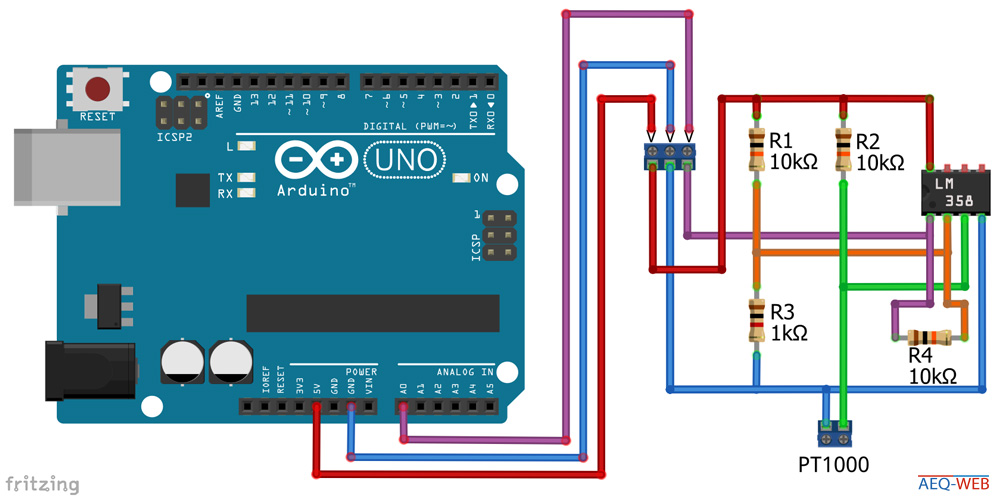
The circuit can be connected directly to the 5V pin of the Arduino voltage regulator. The voltage output from the circuit is connected to the analog input A0. The following circuit shows the same setup including the connection to the Arduino:
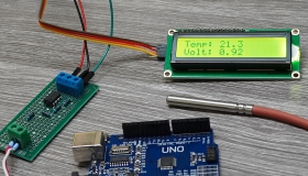
After the circuit is built and connected to the Arduino, it is time to upload the sample code. When the sketch is on the board, the Serial Monitor must be opened. There should be a voltage value and a temperature value displayed. The temperature value is not correct yet, because the circuit is not calibrated yet. The voltage shows the actual measured value at pin A0. For the calibration and thus also correct display of the temperature, two parameters must be adjusted in the software:
vt_factor: The relationship between temperature and voltage
offset: Correction of temperature value
//More Information at: https://www.aeq-web.com/
//Version 1.0 | 03-DEC-2020

const int PT1000_PIN = A0;
const float vt_factor = 1.88;
const float offset = 0;

float temp_c;

void setup() {
  Serial.begin(9600);
}

void loop() {
  int sensorvalue = analogRead(PT1000_PIN);
  float voltage = sensorvalue * (5.0 / 1023.0);
  temp_c = (((voltage * 100) / vt_factor) + offset);
  Serial.print(voltage);
  Serial.print(" V Temp: ");
  Serial.println(temp_c, 1);
  delay(500);
}
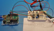
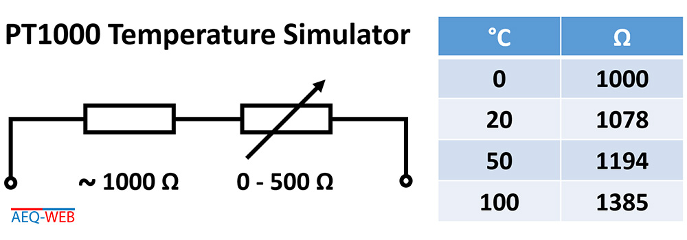
For the calibration of the circuit, a reference resistor is required, which should be as accurate as possible. The PT1000 has a certain resistance value at a certain temperature. This also makes it possible to simulate any temperature value for the circuit. A commercial 1 kiloohm resistor usually does not have exactly 1000 ohms, but a few ohms deviation. In the test setup for this article, the 1 kiloohm resistor was only about 980 ohms according to the ohmmeter. To simulate zero degrees Celsius in the circuit, a small potentiometer of about 500 ohms must be connected in series to the 1 kiloohm resistor. The small potentiometer allows the total resistance to be set to 1000 ohms. If you now want to simulate another temperature value like 100 degrees Celsius to the circuit, the potentiometer must be turned up to exactly 1385 ohms. The following circuit is connected to the corresponding terminals of the transducer instead of the PT1000. This allows a temperature in the range of zero to over 100 degrees Celsius to be simulated continuously:
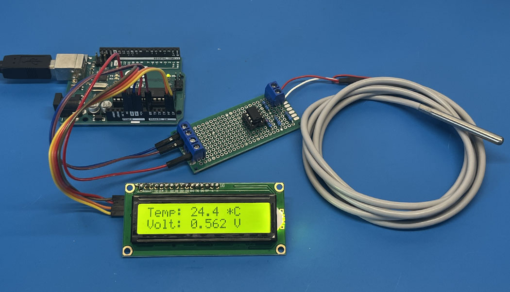
After the entire circuit has been built and connected to the Arduino, a voltage of about 0.9 volts should be present with the PT1000 at room temperature. Since all resistors are subject to certain tolerances, the circuit must always be calibrated once. Instead of the PT1000, the reference resistor is now set to different values and connected to the circuit several times:
1. Voltage at zero degrees
First, the reference resistor is set exactly to 1000 ohms. The Arduino is now simulated a temperature of exactly zero degrees Celsius. Now the displayed voltage must be noted. In the test setup, this voltage was 0.52 volts.
2.Voltage at 100 degrees
In the next step, a temperature of 100 degrees Celsius must be simulated. To do this, the reference resistor is disconnected from the circuit and set exactly to 1385 ohms. The resistor is then reconnected and the displayed voltage is noted. In this case, 2.40 volts were measured.
3. Calculate temperature-voltage factor
So that the Arduino knows which voltage corresponds to which temperature, there is a corresponding conversion factor. If we now subtract the voltage at 0 degrees (0.52 V) from the voltage at 100 degrees (2.40 V), we get the value 1.88. This factor is now defined as vt_faktor in the code. Then the sketch is uploaded again.
4. Set offset
The offset can be set at 100 degrees as well as at 0 degrees. Depending on what is set at the reference resistor, the offset is now set so that the measured temperature in the Serial Monitor corresponds exactly to the simulated temperature. The calibration process is now complete.
5. Connect PT1000
The PT1000 can now be connected to the circuit instead of the reference resistor. The Arduino should now display the correct ambient temperature.
This circuit is a very simple solution for temperature measurement with a PT1000 on the Arduino. The accuracy is therefore about +- 0.5 degrees Celsius. The constant jumping around of the decimal point is caused by the AD-Converter and voltage fluctuations, among other things. To improve this, the circuit could be equipped with another operational amplifier and voltage stabilization. Alternatively, another microcontroller like the ESP32 can be used instead of the Arduino, since here the AD-Converter has a much higher resolution. But attention: The LM358 cannot be operated with 3.3 volts as provided by the ESP32!

The PT100 is a very precise industrial temperature sensor. This article is about building a measuring amplifier for reading a PT100 on the Arduino
read more
With a microcontroller like the Arduino, a small circuit and appropriate software the wind speed can be measured with an anemometer
read more
05.03.2025
25.02.2025
25.02.2025
12.02.2025
AEQ-WEB ist ein Blog von Alex & Andi, der sich mit Elektronik, Funk & Software beschäftigt
read moreAEQ-WEB © 2015-2026 All Right Reserved