Amplifying Analog Voltages with the LM358
05.03.2025
Elektronik | Funk | Software
Der Technik-Blog
05.03.2025

25.02.2025
25.02.2025

12.02.2025
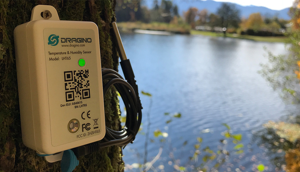
The LHT65 is a device (Thing) for the LoRaWAN and TTN. It is a temperature measuring station consisting of two internal sensors and one external temperature sensor. The external sensor is the well-known DS18B20. Internally there is a combined sensor which can measure temperature and humidity. The sensor is well suited if you want to measure the temperature of a lake, for example. But also on high mountains, where extreme weather conditions dominate, the sensor is well suited, because it can be operated with a battery for many years. This article describes the installation of the sensor and the connection to the LoRaWAN network TTN. The Dragino LG-02 is used as gateway. Basically any other gateway or existing public gateways can be used.
Warning: This article is outdated and not compatible with TTN V3. There is an update to the project in this article.
The sensor has a built-in officially non-replaceable battery which should have a life of 8 to 10 years according to the manufacturer. Inside is a circuit board with a STM32 microcontroller which is extremely energy efficient and the well-known SX1276 LoRa chip from Semtech. On the backside there is a 4-pin connector, which can be used to update the firmware. In addition, a serial connection can be established via this interface which is used to configure the sensor. On the front side there is a multicolored status LED, a QR code and the type description. On the bottom is a button and a jack connector for the external sensor (DS18B20).
The sensor is already preconfigured with the corresponding keys on delivery. These keys must be entered in TTN or another LoRaWAN network. Afterwards the sensor can be activated by a long press on the button. The sensor starts with a JOIN request and tries to communicate with the LoRaWAN network via OTAA. Attention: OTAA is not directly supported by some gateways, because they often work on only one frequency (Single Channel Gateway) or two static frequencies (e.g. Dragino LG-02). Either the sensor is configured accordingly for these gateways, or you switch to the ABP mode. Note: In this article, the sensor is connected to the TTN via ABP which is easier than OTAA, because the entire JOIN request process is not necessary. ABP also has disadvantages in security compared to OTAA, but this is negligible with a simple sensor that does not transmit sensitive data.
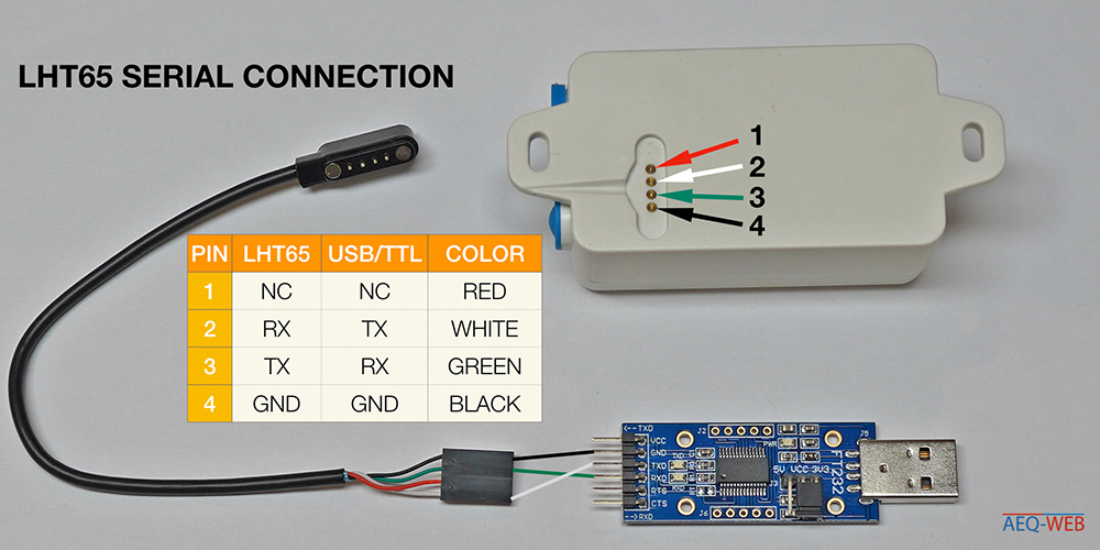
The sensor can be configured via the serial interface. A corresponding cable from the sensor to the jumper wire connection is also included. A TTL adapter (USB -> RS232) is required to establish a connection to the computer. In addition, this cable is used to update the firmware (ST-Link Programmer required). Alternatively the Arduino can be used as a serial bridge. The following figure shows the pin assignment between sensor and RS232 adapter:
First of all you have to register with TTN (The Things Network). A gateway is required to operate the sensor. This does not necessarily have to be operated by yourself, but especially for beginners and for easier troubleshooting a separate gateway is highly recommended. Otherwise, most public gateways in the neighbourhood can be used. Basically a registered sensor or application can access any gateway, which is connected to TTN and set to the same configuration parameters (SF, coding rate, bandwidth, frequency....).
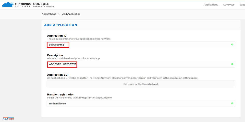
In the first step a new application must be created in TTN. In this application one or more devices (Things) are registered. Here two freely selectable parameters (Application ID, Description) must be assigned. These parameters have no further effects on the end devices or gateways.
KeysThe keys can either be read off the enclosed sticker and entered accordingly at TTN or read directly from the sensor via a terminal client. Since the keys are very long and even the smallest mistake leads to a connection termination, it is quite practical to simply copy the parameters from the terminal. Because the "Device Address" has to be changed later anyway, a serial connection and configuration is always necessary in this case. As shown in the picture above, the sensor is connected to the USB adapter.A terminal software establishes a connection with a baud rate of 9600 via the COM port. Then enter the following character in the terminal and press Enter:
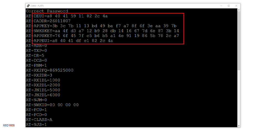
123456Answer: Correct Password
AT+CFGThis command outputs the entire configuration including all keys. As shown in the following screenshot, you copy the red marked keys to a text editor:
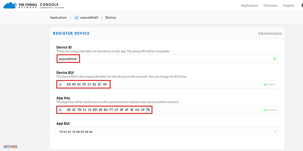
After all necessary keys have been read out and an application has been created, the first device can be registered there. The device ID is again freely selectable and has no direct effect on the end device. Then the Device EUI (DEUI) and the App Key (APPKEY) must be entered from the device in TTN. Both keys can be copied directly from the terminal into the input field. The App EUI is initially generated automatically by TTN and can be changed after the sensor has been created.
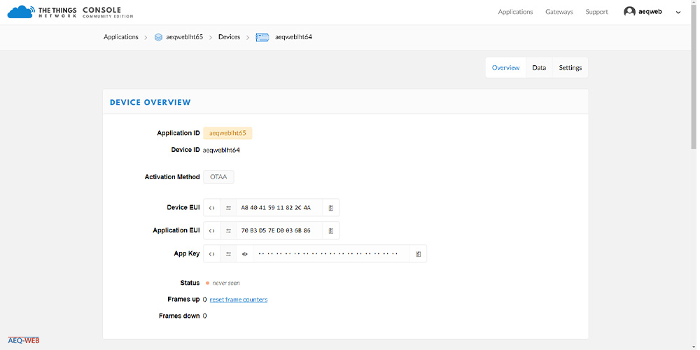
After the first keys and descriptions have been entered, the sensor is stored in the TTN and is displayed accordingly in the Device Overview.
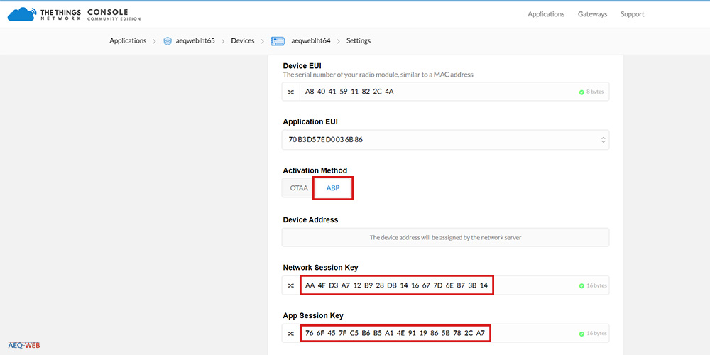
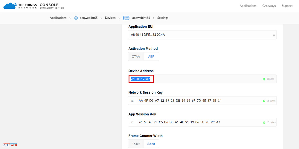
Under Applications -> APP_NAME -> Devices -> DEVICE_ID -> Settings a description can be assigned to the newly added device. Afterwards the Activation Method must be changed from OTAA to ABP as shown in the next screenshot. Additionally the Network Session Key (NWKSKEY) and the App Session Key (APPSKEY) must be entered in ABP mode. Both keys can be copied from the terminal again.
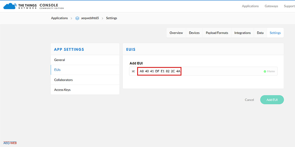
In order to get the sensor data into the correct application, the corresponding EUI must be added. Another EUI can be added to the application under Applications -> APP_NAME -> Settings -> EUIS. Again, the APPEUI is copied from the terminal into the input field. Two EUIS should then be displayed in TTN. The second already existing EUI, which was automatically generated by TTN in step 3, can be deleted. Alternatively the EUI generated by TTN can be changed in the sensor, which would save this step.
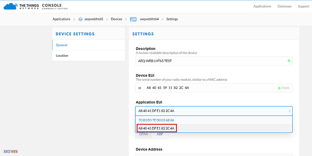
After the application EUI has been added, it must also be assigned to the sensor. Under Applications -> APP_NAME -> Devices -> DEVICE_ID -> Settings the previously entered correct EUI is assigned to the device and stored.
In the same window as in step 7, the Device Address must be copied to clipboard. This short address is copied to the device via the terminal in the next step.
In the last step, the sensor must be reconfigured to ABP mode via the terminal. In addition the device address must be changed. The following commands are sent to the sensor via the terminal:
1. Enter Password:
123456
2. Change into ABP-Mode:
AT+NJM=0
3. Disable Adaptive Data Rate:
AT+ADR=0
4. Set Data Rate (5 = EU Band):
AT+DR=5
5. Set transmission interval (600 000 millis = 10 min):
AT+TDC=600000
6. Set transmission frequency to 868.1 MHz:
AT+CHS=868100000
7. Change Device Address to the default of TTN:
AT+DADDR=11 22 33 AA
*11 22 33 AA must be changed to the address determined in step 8
8. Reboot controller:
ATZ
The following picture shows a screenshot of the terminal. After each of the previous inputs an OK must be given by the sensor.
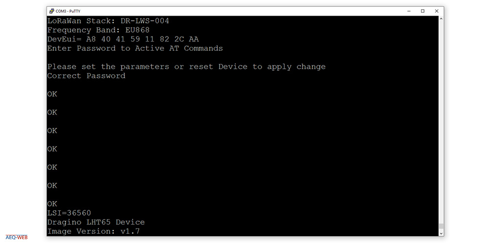
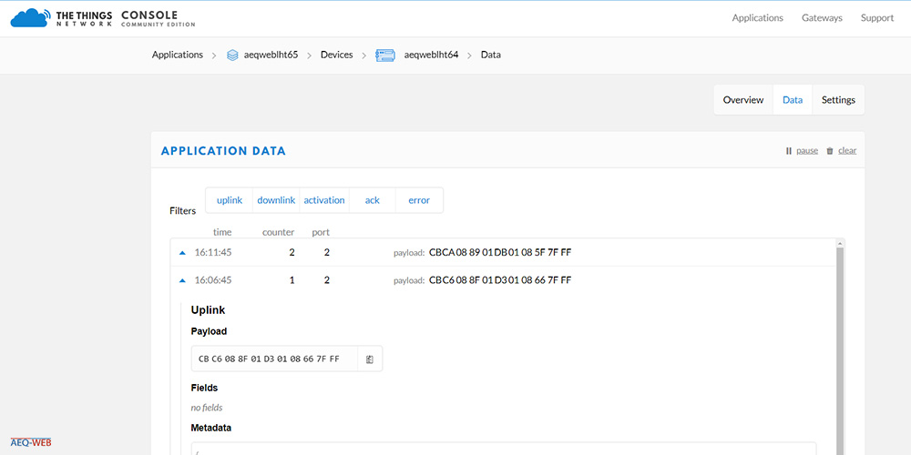
After all parameters have been set correctly both in TTN and at the sensor, a first packet should arrive in TTN immediately after the last command (ATZ). In the screenshot below you can see the received packet with the payload. The payload contains all measured values, battery voltage etc. already decoded in hexadecimal packets. In order to get the individual measured values from the payload, an appropriate decoder is needed.
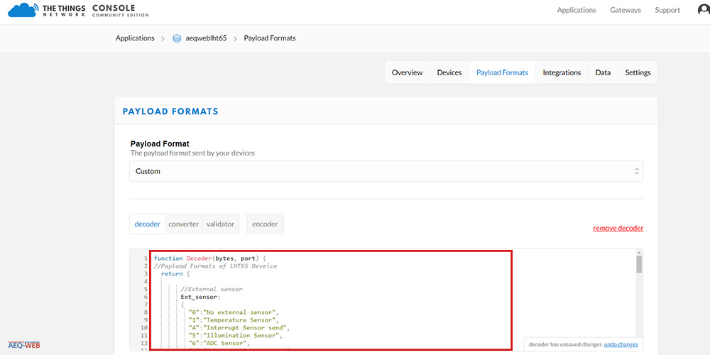
The encoder converts the received payload into the individual values. LoRaWAN tries to keep the size of the data to be transferred (payload) as small as possible. JSON or plain text transmission should therefore be avoided. Depending on the sensor there is usually an already finished code from the manufacturer which is copied into the decoder field. The code is similar to a C++ programming as known from the Arduino world. By decoding the values, the individual data records can be passed on from the TTN, for example in JSON format, to the corresponding application server. The decoder for the LHT65 sensor is available here: LHT65 Payload Decoder
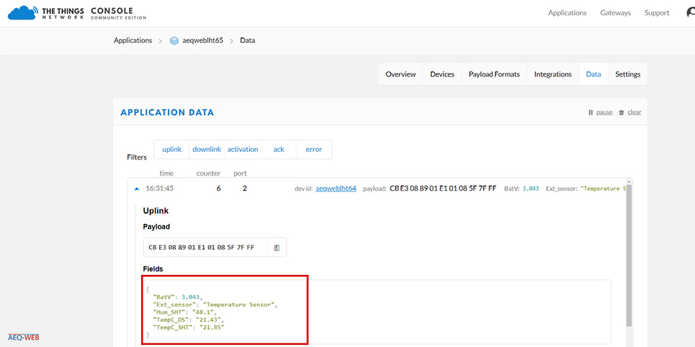
After the decoder has been integrated into your TTN application, from now on all received values are displayed in plain text as shown in the screenshot below. At this point the sensor setup is successfully completed and can be processed by the other servers/applications via the different interfaces.

The LoRaWAN FRM payload includes numerous headers, the encrypted payload, and an integrity code. This article explains the structure of an uplink message
read more
The UDP packet forwarder developed by Semtech handles the data transmission of the received packets from the LoRaWAN gateway to the network server
read more
05.03.2025
25.02.2025
25.02.2025
12.02.2025
AEQ-WEB ist ein Blog von Alex & Andi, der sich mit Elektronik, Funk & Software beschäftigt
read moreAEQ-WEB © 2015-2026 All Right Reserved