Amplifying Analog Voltages with the LM358
05.03.2025
Elektronik | Funk | Software
Der Technik-Blog
05.03.2025

25.02.2025
25.02.2025
12.02.2025
Ventilators, such as those used in industry and computers, have a speed sensor. This sensor generates a so-called tachometer signal, which can be used to monitor the speed and functionality of the fan. This article is about the processing of the tachometer signal with the Arduino.
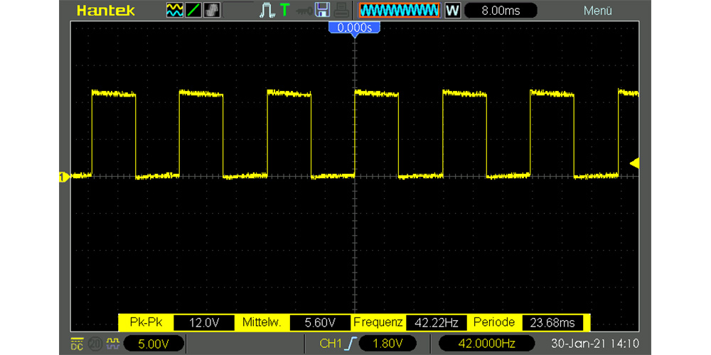
The speed sensor usually consists of a Hall sensor and a transistor that switches the output signal. In most fans, the sensor is triggered two times per rotation and therefore outputs two pulses on the signal line. In order for the signal to be processed by a microcontroller or oscilloscope, a positive voltage must be present on the signal line. As soon as the sensor switches, the voltage is then pulled down and a low signal occurs. If the sensor is not active, the full voltage is present on the line, which is interpreted as a high signal. To avoid a short circuit or to keep the current as low as possible, a resistor must be connected between the signal line and the positive pole. The following screenshot shows the tacho signal of the fan:
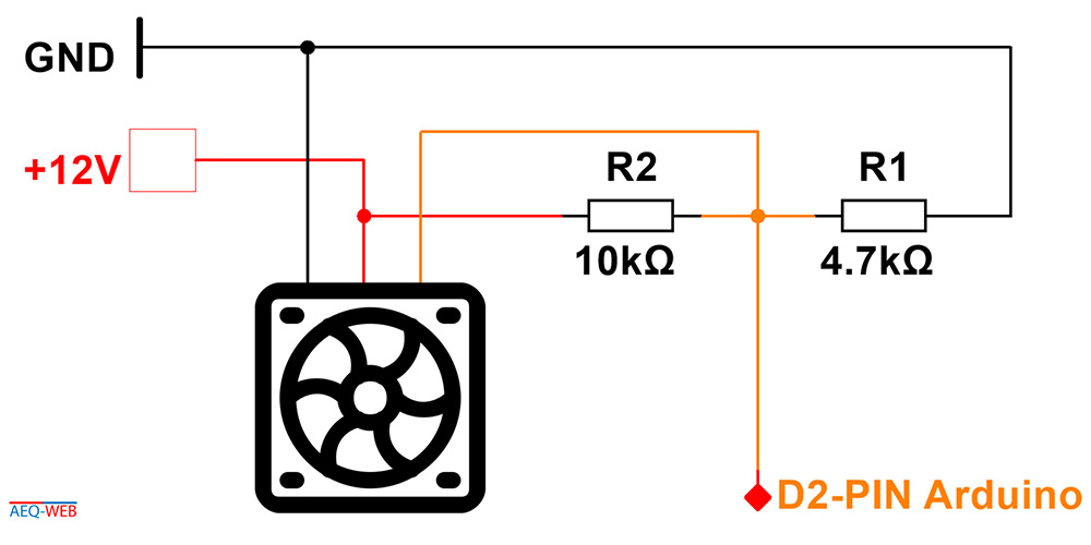
As already mentioned, a pull-up resistor (R2) is needed to generate a digital signal. Since most fans are operated with 12 volts, the signal voltage is also the same. However, this is much too high for a microcontroller and must be adjusted so that at the maximum operating voltage, the signal voltage is no more than 5 or 3.3 volts, depending on the microcontroller. Another resistor (R1) is connected in series with R2 to form the voltage divider, which reduces the level voltage accordingly. The tachometer signal line is further routed through the voltage divider to the digital input of the microcontroller. **Arduino Lüfter Drehzahl Signal auswerten
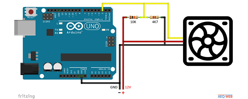
The Arduino must be connected to the same ground of the fan. If the signal is evaluated via interrupts, it must be ensured that the pin also supports this. With the Arduino Uno only pin 2 or 3 can be used for this.
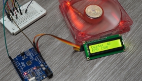
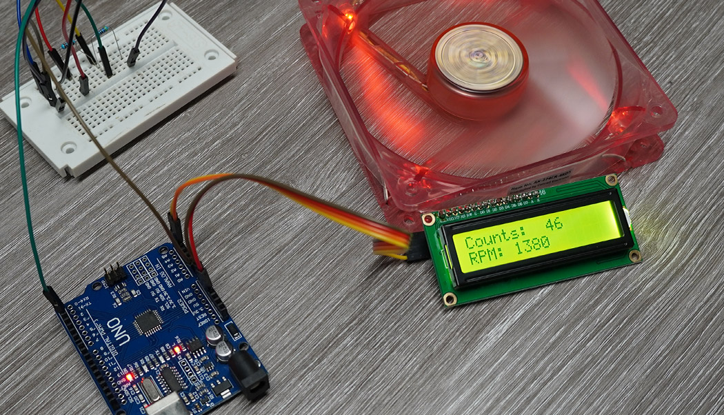
The software for the measurement is very simple. As with the Anemometer project the simplest solution here is to work with interrupts. The example code activates the counting of flank changes (low to high) with interrupts and counts up the value per flank. After one second the counting is stopped and the interrupt function will stop the measurement. Since two flanks are to be expected from the fan per rotation, the counter must then be divided by two. The measuring time is one second, so that the rotations per minute (RPM) can be calculated, the previously divided counter must be multiplied by 60. The results are then displayed in the Serial Monitor.
//More information at: https://www.aeq-web.com/

const int SensorPin = 2;  //Define Interrupt Pin (2 or 3 @ Arduino Uno)

int InterruptCounter, rpm;

void setup(){
  delay(1000);
  Serial.begin(9600);
  Serial.print("Counting");
}

void loop() {
  meassure();
}

void meassure() {
  InterruptCounter = 0;
  attachInterrupt(digitalPinToInterrupt(SensorPin), countup, RISING);
  delay(1000);
  detachInterrupt(digitalPinToInterrupt(SensorPin));
  rpm = (InterruptCounter / 2) * 60;
  display_rpm();
}

void countup() {
  InterruptCounter++;
}

void display_rpm() {
  Serial.print("Counts: ");
  Serial.print(InterruptCounter, 1);
  Serial.print(" RPM: ");
  Serial.println(rpm);
}
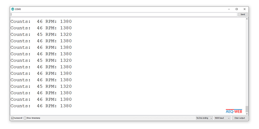
The sample code provides usable results, which showed a deviation of around 60 RPM for the fan used in this test. One reason for this is the rather short measurement time. If the measurement time is extended to about 3 seconds, the deviation is significantly lower due to a more accurate average value.
PWM is often used to control the speed. As soon as PWM is used, no matter if on the positive line or on the ground, the tachometer signal will be disturbed. The problem is that the internal Hall sensor is on the same power supply. The result of the output signal is then PWM and the tacho signal. There are the following solutions to avoid these problems with 3-pin fans:

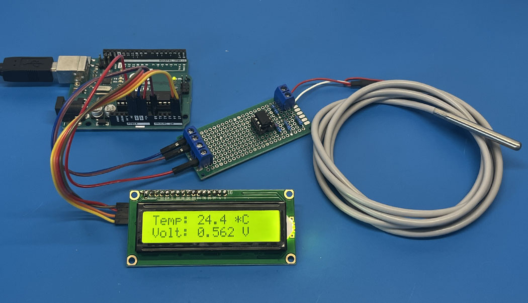
The PT100 is a very precise industrial temperature sensor. This article is about building a measuring amplifier for reading a PT100 on the Arduino
read more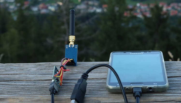
On this page we will show you how to make a data transfer with the CC1101 and an Arduino. Wiring plan and libraries are available on AEQ-WEB
read more
05.03.2025
25.02.2025
25.02.2025
12.02.2025
AEQ-WEB ist ein Blog von Alex & Andi, der sich mit Elektronik, Funk & Software beschäftigt
read moreAEQ-WEB © 2015-2026 All Right Reserved