Amplifying Analog Voltages with the LM358
05.03.2025
Elektronik | Funk | Software
Der Technik-Blog
05.03.2025

25.02.2025
25.02.2025
12.02.2025
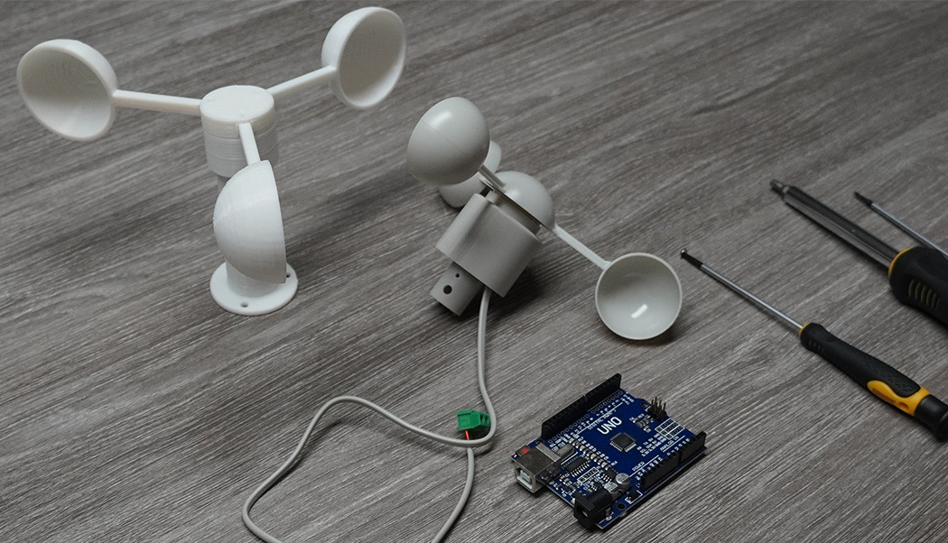
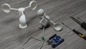
In a simple weather station the wind speed is measured with an anemometer. The anemometer emits a short pulse with each rotation, which is counted up with a microcontroller over a certain period of time. The wind speed can be measured with an appropriate conversion factor. This updated article is about reading out an anemometer with an Arduino Uno. The software outputs the currently measured wind speed every three seconds over the serial monitor.
The anemometer consists of an easily rotatable spoon wheel, which is constantly moved by the wind. There is a small magnet on the axis, which always rotates with it. As sensor a reed contact is used, which closes the electric circuit every time the magnet passes the sensor. This generates an impulse with each rotation. The advantage of this variant is the simple construction with only two wires. A separate power supply is not required. A disadvantage is however the mechanical switch (reed contact). This will be worn out over the years due to the constant switching, which can lead to a failure or to disturbances of the measurement after some years. Alternatively the anemometer can be converted to an optical evaluation (light sensor) or inductive evaluation (Hall sensor). With an appropriate electronic circuit the mechanically caused measuring errors of the reed contact can be compensated quite well.
Since it is basically only a switch, the anemometer is connected similar to a push button. The resistor of 10 kiloohm functions here as a pull-down resistor, which pulls the level in the open circuit to ground. Some microcontrollers have a built-in pull-down resistor which can be activated by software. In this case the resistor could be omitted. The reed contact can be connected directly via the 5 Volt pin. The same circuit can also be operated with 3.3 volts.
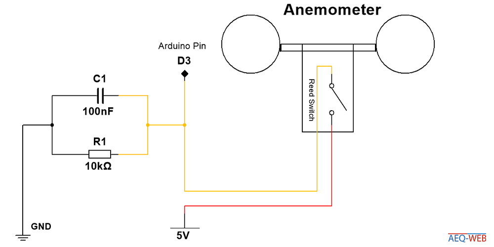
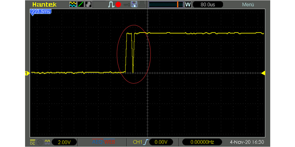
The capacitor in parallel to the resistor is used to briefly catch the voltage from the digital input. Over the years the reed contact will be worn out mechanically. Dirt and metal particles on the contacts can cause the contact to emit several impulses in fractions of a millisecond until the magnet has really tightened it. Since the microcontroller counts the signals via interrupts, it also reacts extremely fast to an edge change. The consequence would be a multiple counting of pulses, although there was actually only one. This would then lead to a clearly excessive wind speed in the evaluation. Since the capacitor always needs a short time to charge, it takes the voltage shortly before the digital pin gets the voltage. Exactly this time is sufficient to compensate for such mechanically caused measurement errors. Afterwards, the capacitor must also discharge again quite quickly, otherwise this also leads to a measurement error. A capacity of 100 Nanofarad is therefore a good compromise. The following figure shows such a mechanical measurement error from an old anemometer:
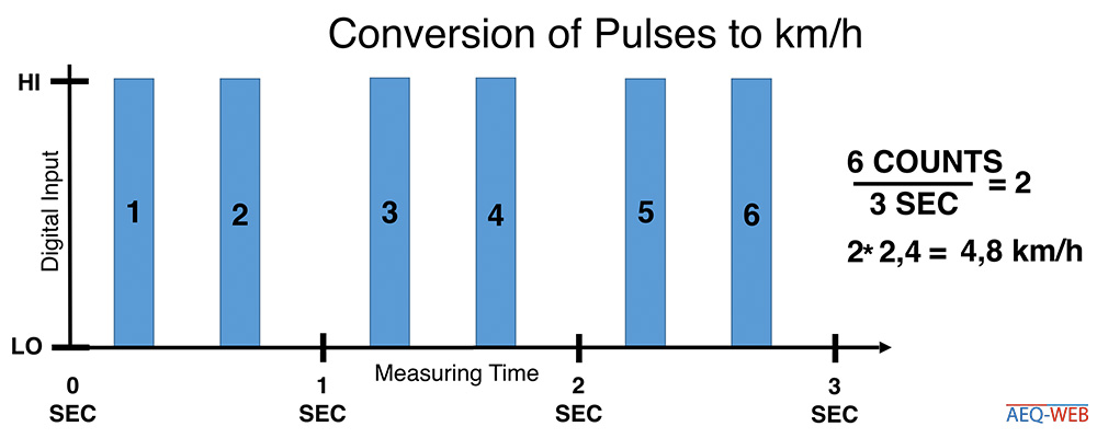
The microcontroller receives one pulse per rotation. According to the manufacturers data sheet this means that one turn per second equals a wind speed of 2.4 km/h. The software would simply have to count the pulses that come exactly in one second and multiples them with a factor of 2.4. However, since a measuring time of one second provides hardly any useful results, this should be increased to a few seconds. Three seconds are enough for a test. In production, use a measuring time of 30 seconds or one to get good results. The main function of the software is therefore to count the individual pulses and divide them by the measuring time. The result must then be multiplied by a factor of 2.4. The result is the wind speed in kilometers per hour.
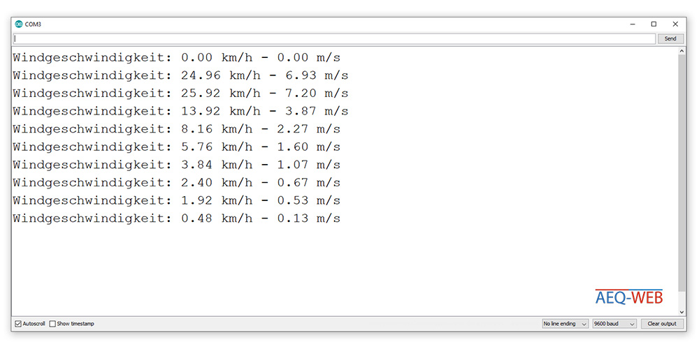
As already mentioned, the main task of the software is to count the individual pulses in a time window and convert them into a speed. To read in a digital input continuously via the software and to evaluate it with comparison operations is not very efficient. The better solution are interrupts. Before each measurement the pulse counter is set to zero. Then the interrupt is activated on the connected pin in RISING-mode. If a change (LOW to HIGH) occurs at the digital input, the controller triggers an interrupt. At each interrupt the pulse counter is now added by the value "one". Although there is a delay of several seconds after the interrupt is activated and the software is "frozen", interrupts are counted as well. After the measuring time has expired, the interrupt at the pin is cancelled and the current pulses are converted to the wind speed with the time and conversion factor. Afterwards an output in the Serial Monitor is generated. More information about interrupts can be found ""HERE"". The following screenshot shows the Serial Monitor of the Arduino IDE with actual measured values:
//More Information at: https://www.aeq-web.com/
//Version 2.0 | 11-NOV-2020

const int RecordTime = 3; //Define Measuring Time (Seconds)
const int SensorPin = 3;  //Define Interrupt Pin (2 or 3 @ Arduino Uno)

int InterruptCounter;
float WindSpeed;

void setup()
{
  Serial.begin(9600);
}

void loop() {
  meassure();
  Serial.print("Wind Speed: ");
  Serial.print(WindSpeed);       //Speed in km/h
  Serial.print(" km/h - ");
  Serial.print(WindSpeed / 3.6); //Speed in m/s
  Serial.println(" m/s");
}

void meassure() {
  InterruptCounter = 0;
  attachInterrupt(digitalPinToInterrupt(SensorPin), countup, RISING);
  delay(1000 * RecordTime);
  detachInterrupt(digitalPinToInterrupt(SensorPin));
  WindSpeed = (float)InterruptCounter / (float)RecordTime * 2.4;
}

void countup() {
  InterruptCounter++;
}

With a microcontroller like the Arduino, a small circuit and appropriate software the wind speed can be measured with an anemometer
read more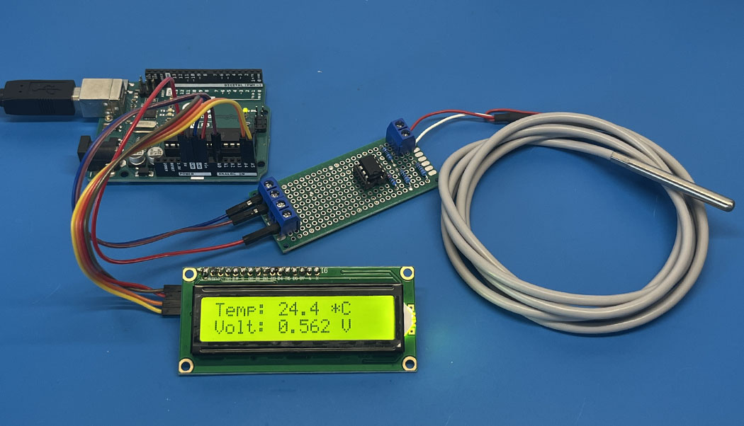
The PT100 is a very precise industrial temperature sensor. This article is about building a measuring amplifier for reading a PT100 on the Arduino
read more
05.03.2025
25.02.2025
25.02.2025
12.02.2025
AEQ-WEB ist ein Blog von Alex & Andi, der sich mit Elektronik, Funk & Software beschäftigt
read moreAEQ-WEB © 2015-2026 All Right Reserved