Amplifying Analog Voltages with the LM358
05.03.2025
Elektronik | Funk | Software
Der Technik-Blog
05.03.2025

25.02.2025
25.02.2025
12.02.2025
Every day hundreds of radiosondes or weather balloons fall from the sky worldwide. This article is about uploading a new firmware, which allows to use the probe (Vaisala RS41) for amateur radio. The firmware used in this project is the software from OM3BC.
The following tools are required:
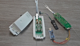
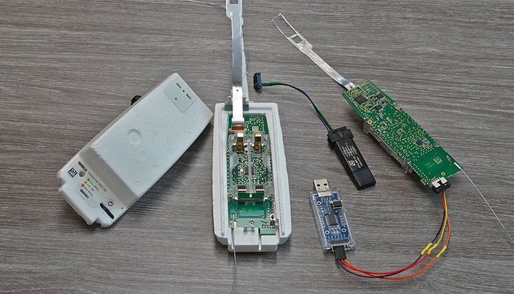
The sonde consists of a circuit board with many individual components. Everything is controlled centrally by a microcontroller, which communicates with individual components such as GPS, transmitters, sensors, etc. The power supply comes from two 1.5 volt lithium batteries. Due to their low weight and higher capacity, these cells are more suitable than conventional batteries. Of course the system can also be operated with conventional alkaline batteries. Via the XData connector the microcontroller can be flashed with new software. Afterwards the sonde is connected to the same port, but configured on other pins via the serial interface.
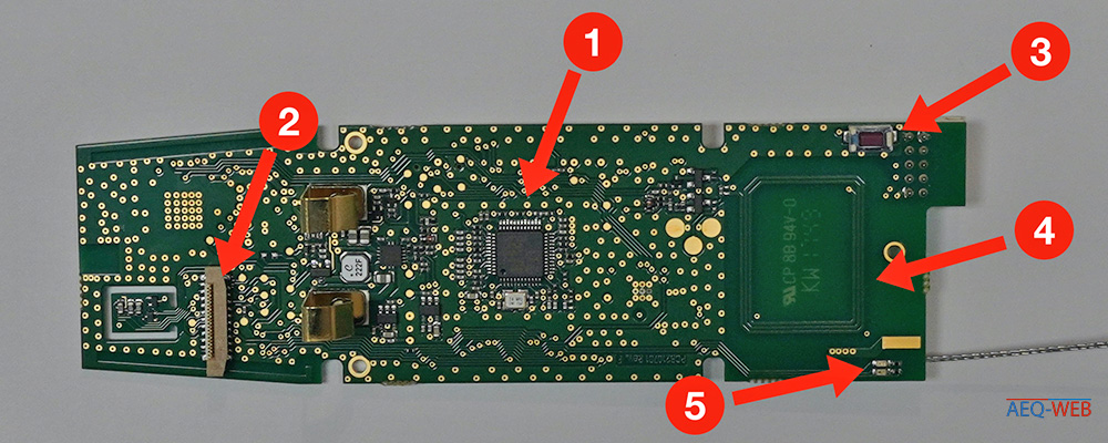
On the upper side of the board, directly below the battery holder, is the microcontroller (STM32F100C8T6) from STMicroelectronics (1). On the left side after the battery holder is the connector for the external sensors (2). On the right side there is a button (3) for switching on the probe. The coil of the NFC antenna (4) is located directly under the button. Directly above the transmitting antenna there are two LEDs (5) which indicate the current status of the probe.
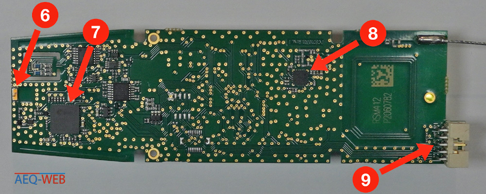
On the bottom side are some ICs and memories. In the center left is a small GPS antenna (6). Not far from this antenna is the GPS controller (7) from U-Blox (UBXG6010), which communicates serially with the main controller. On the right side is the transmitter unit (8) for data transmission. Here a controller from Silicon Labs (SI4032) is used, which can transmit radio signals of about 300 to 900 MHz. On the far right is the 10-pin connector for programming the probe.
Basically, there are many possibilities how the probe can be further used. Common applications are radio temperature sensor, GPS tracker or APRS applications. The firmware of OM3BC is specially designed for radio amateurs who want to do some APRS in the 70 cm band. The probe can either send APRS messages with the current position or transmit sensor data via CW and RTTY.
A very big problem is the programming port (XData socket). The pitch here is not 2.5mm as usual, but 2mm. Usual jumper wire cables, as known from the Arduino world, do not fit in here. Either you bend the connector and use the usual jumper wire cables or you simply solder the cables accordingly. Nevertheless, the matching connector can be ordered from various specialist dealers. The exact type is: Amphenol 89361-710SLF.
To use the probe privately, the firmware must be changed. OM3BC has developed a corresponding firmware which is flashed to the probe via the ST-Link Programmer. The firmware will be flashed to the probe via the STSW-LINK009 (ST-Link) software.
ST Link is the software used to load the program from OM3BC to the probe. ST-Link is downloaded and installed free of charge from the STM-Website. The Programmer Stick can then be connected to the computer via USB. You may receive a message that the firmware on the Programmer is out of date and needs to be updated. The update can be done directly via this software. Then the probe is opened and prepared for programming.
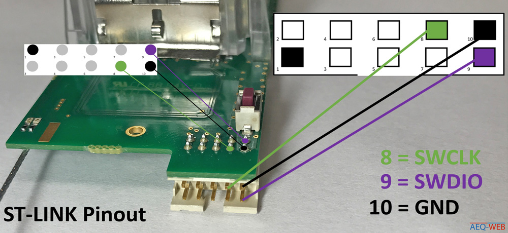
As already mentioned, the connection to the programmer or TTL adapter is a bit difficult. If the probe is powered with batteries, only three cables are needed for flashing: 10=GND, 9=SWIDO, 8=SWCLK.
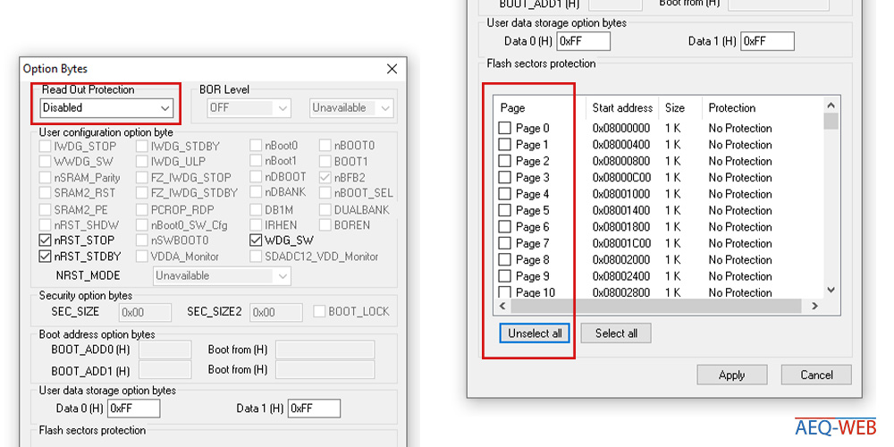
If ST-Link has recognized the microcontroller, an error message usually appears stating that the memory cannot be read. The manufacturer has activated a protective mechanism here that makes it impossible to read the software. Since the firmware will overwrite anyway, this warning is unnecessary.
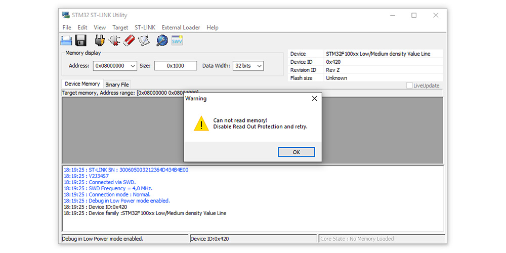
Under Target->Option Bytes a window opens where the "Read Out Protection" is set to "Disabled" at the top. Afterwards all checkboxes under "Flash sectors protection" are removed in the same window. To do this, simply click on "Unselect all" and save and close with "Apply".
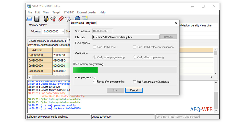
The complete new program of OM3BC for the probe is available as a HEX file on its Website. This file (rtty.hex) must be opened in ST-Link Utility.
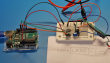
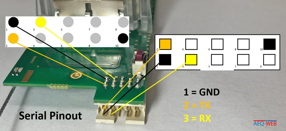
After the software has been successfully uploaded, it must now be configured. Again, a serial connection must be established via the XData port. Either you use a microcontroller like the Arduino Uno, or you have a computer with a serial port. Another very convenient solution is a USB-to-TTL converter. This adapter converts the USB interface into a serial RS232 interface. Attention: The probe works with a logic level voltage of 3.3 volts. Some adapters work with this voltage or the level voltage is adjustable. If the level voltage is at 5 Volts, you can put a simple voltage divider on the TX line from the TTL converter to reduce the voltage to 3.3 Volts. More information about this in the article: (voltage divider). The following figure shows the necessary wiring for a serial connection. Here, too, the probe must be switched on and supplied with the operating voltage via the batteries.
A terminal is required to access the Sonde. Putty is a very popular software which is well suited for such applications. In Putty or another terminal client the appropriate COM port must be selected and the baud rate must be set to 9600 Baud.
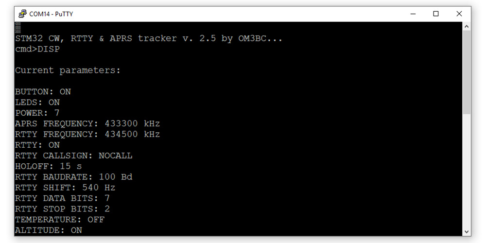
With the "help" command, the probe outputs all possible configuration commands that can be used. Important is the "DISP" command, which outputs the current configuration. After each setting of new parameters, the "SAVE" command must be sent so that the setting remains permanently saved. A list with all explained commands can be found here: OM3BC RS41 Firmware & Commands

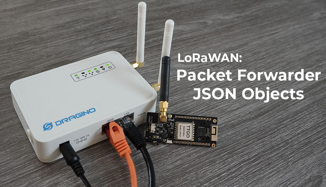
The packet forwarder in a LoRaWAN gateway sends the uplink & status packets as JSON to the network server after the 12 hexadecimal bytes
read more
Every day hundreds of meteorological radiosondes fall from the sky. In this article we convert a radiosonde into a GPS tracker for APRS, RTTY & CW
read more
05.03.2025
25.02.2025
25.02.2025
12.02.2025
AEQ-WEB ist ein Blog von Alex & Andi, der sich mit Elektronik, Funk & Software beschäftigt
read moreAEQ-WEB © 2015-2026 All Right Reserved