Amplifying Analog Voltages with the LM358
05.03.2025
Elektronik | Funk | Software
Der Technik-Blog

05.03.2025

25.02.2025
25.02.2025

12.02.2025
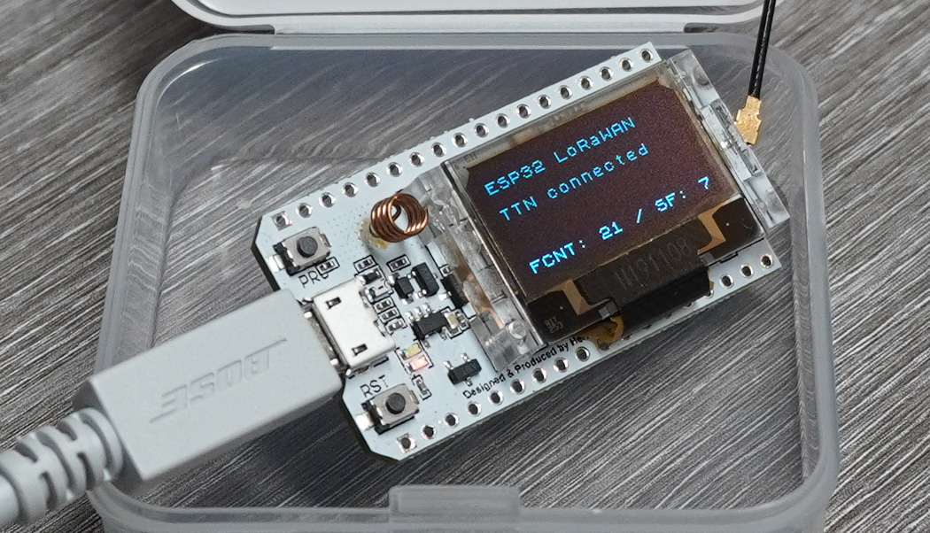
The ESP32 LoRa board from Heltec is very powerful and versatile. The special feature of the board is the built-in LoRa technology and the very good range of LoRa. LoRa can communicate in direct mode (e.g. from ESP32 to ESP32) as well as in different LoRaWAN networks like TTN. Basically all LoRaWAN standards are supported here, as this is primarily only due to the software. This article is about the communication with the ESP32 to the LoRaWAN network TTN in ABP mode.
Used Library: Arduino LMIC (from MCCI Catena) | Version 3.2.0
Register Arduino/ESP32 at TTN (ABP)
Source Code ESP32 LoRaWAN (ABP)
In order for the ESP32 to communicate with TTN, a gateway with a corresponding connection to the TTN network is still required. An own LoRaWAN gateway is not necessary, because the software is compatible with all LoRaWAN gateways that communicate to TTN. For troubleshooting, it is therefore highly recommended to have your own gateway, because by accessing this hardware you get a lot more information, which is very helpful for troubleshooting. In addition, it can also be used to determine if the packets are arriving at TTNs network server. LG-02 LoRaWAN gateway was used for this project.
In addition to ABP, there is also the OTAA procedure for logging on to the LoRaWAN network and sending data. The OTAA procedure is more secure than ABP, but also more "complicated". ABP does not require a JOIN request to join the LoRaWAN. No bidirectional connection is established, which means that maximum compatibility is achieved and therefore any single channel gateway can receive and forward received data. The transmit frequency and all related parameters are fixed and can only be changed on the device itself and not by TTN or via the ADR. The biggest advantage is therefore the simpler communication and the highest compatibility with all gateways. The ESP32 and the software/library used in this article is of course also compatible with OTAA and can be reprogrammed accordingly.
There are many libraries for LoRaWAN, most of them are further developments or modifications of the original LMIC library. The original LMIC library consists of developments from IBM and enables the communication with the LoRa hardware and LoRaWAN. The code was further developed and made compatible for the TTN as well as for the Arduino. The LMIC repository is no longer maintained and is thus considered obsolete. Both TTN and the developers of this library recommend the MCCI library as the alternative with the highest compatibility. The MCCI library also serves as a base for this project and will be adapted accordingly for use on the ESP32 LoRa board. In general, this library and all other libraries based on the LMIC library basically consist of the following major subcomponents:
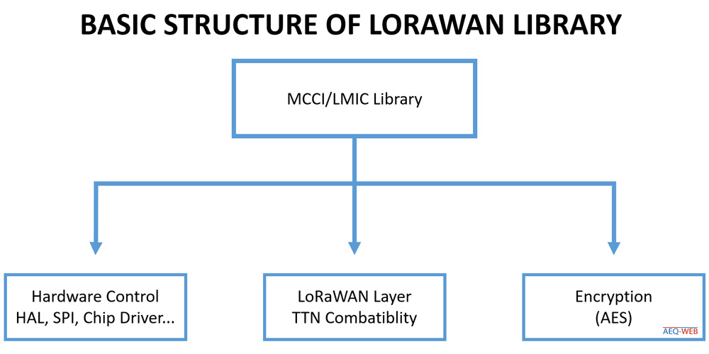
Hardware Controller: An essential part of the software is the correct control of the hardware. This includes the control of the LoRa chip as well as the control of SPI and other pins.
LoRaWAN & TNN: LoRa itself is only the physical interface for wireless data transmission. LoRaWAN uses this radio technology, but behind it is only software. For LoRaWAN to work, a network is needed that takes care of decoding/encoding, routing and forwarding the data from the LoRaWAN network. TTN (The Things Network) is probably the best known and largest, but not the only LoRaWAN network. The microcontroller has to provide the data in certain formats and keys for the communication to the gateways and the LoRaWAN network to work.
AES Encryption: LoRa mainly relies on an AES encryption. It is a symmetrical encryption method, which means that the keys for encryption and decryption are the same on both sides. The task of the library is to calculate all keys in such a way that they can also be decrypted again by the network. The most important key is the application key or app session key, because this encrypts the data from the end device to the application and cannot be read by a gateway or other systems in between. AES is generally considered to be quite secure and is a good base for security in IoT devices.
Since the library is basically intended for use on the Arduino, it does not work immediately on the ESP32. The main problem for this is the different pinout of the interfaces and IO pins between Arduino and ESP. The Heltec ESP32 LoRa (V2) board has the following pinout to the LoRa chip:
| Description | Pin on ESP32 |
|---|---|
| SCK | 5 |
| MISO | 19 |
| MOSI | 27 |
| Description | Pin on ESP32 |
|---|---|
| NSS | 18 |
| DIO 0 | 26 |
| DIO 1 | 35 |
| DIO 2 | 34 |
| RST | 14 |
A very important setting of the library is the adaptation to the European frequency band. In the main folder of the library there is another folder with "project_config". In this folder is the configuration file " lmic_project_config.h". Here the second line (#define CFG_eu868 1) is commented out. The line below is commented (//#define CFG_us915 1) . From now on the library works in the Europe frequency band on 868 mHz.
// project-specific definitions
#define CFG_eu868 1
//#define CFG_us915 1
//#define CFG_au915 1
//#define CFG_as923 1
//#define LMIC_COUNTRY_CODE LMIC_COUNTRY_CODE_JP	/* for as923-JP */
//#define CFG_kr920 1
//#define CFG_in866 1
#define CFG_sx1276_radio 1
//#define LMIC_USE_INTERRUPTS
For the software to work properly, some keys are needed. Some of the keys can be generated by yourself. The easiest way is to let TTN generate the keys for the respective device automatically and insert them into the sample code. Since the setup is the same for all development boards (Arduino, ESP32, TTGO etc.), there is another detailed article on the blog about Setup a Device at TTN (ABP mode).
The ABP sample code supplied in the library is used as the base. Since the software is intended for operation on the Arduino, some hardware pins must be changed in the software. In addition, the device must already be registered with TTN in advance so that all keys can be integrated into the sample code. The character set "Hello World!" is transferred as payload.
1. Customize the keys
Three keys are needed for the communication to work. The keys NWKSKEY, APPSKEY and DEVADDR are inserted or edited in the upper lines from the sample code. Here is an example:
static const PROGMEM u1_t NWKSKEY[16] = { 0x1D, 0x1A, 0x15, 0x1F, 0x38, 0x03, 0xC0, 0xA1, 0x7C, 0xA7, 0xAC, 0x0C, 0x4A, 0x49, 0x3B, 0x2B };
static const u1_t PROGMEM APPSKEY[16] = { 0xEC, 0x19, 0x82, 0xA2, 0xC7, 0x2D, 0xFC, 0x42, 0xD7, 0x35, 0xB8, 0x3E, 0xFE, 0xC0, 0x0F, 0xFE };
static const u4_t DEVADDR = 0x260121A4;
2. LoRa Chip Pin Mapping
In addition to the serial communication lines (SPI), the LoRa chip on the ESP32 has other digital I/O pins (DIOs, RST...) that are necessary for control. The following excerpt is already adapted to the LoRa pins on the ESP32 LoRa Board V2 and can be replaced directly in the sample code:
const lmic_pinmap lmic_pins = {
  .nss = 18,
  .rxtx = LMIC_UNUSED_PIN,
  .rst = 14,
  .dio = {26, 34, 35},
};
3. Change SPI Pins
As already mentioned the original library was developed for Arduino boards. Since the Arduino has only one SPI interface with fixed pins, these pins must be adapted accordingly on the ESP32. The following line can be copied directly into the next line after "void steup(){".
void setup() {
  SPI.begin(5, 19, 27, 18);
  ....
The controller now knows which pins have to be used to open an SPI connection and how it can communicate with the LoRa chip.
The sample code sends out each data packet on a different channel by default. A total of 8+1 channels are available. It starts with the transmission on channel 0. In the next pass, another data packet is transmitted on channel 1. After nine transmissions, the software starts again with channel 0. The 8-channel LoRa gateways have no problems with the constant frequency change. However, if you work with a Single -Channel-Gateway, you will only receive every eighth data packet. If you insert the following lines in the code, you can limit the transmission to one channel:
  //Add this lines inside void setup():

  //LMIC_disableChannel(0);
  LMIC_disableChannel(1);
  LMIC_disableChannel(2);
  LMIC_disableChannel(3);
  LMIC_disableChannel(4);
  LMIC_disableChannel(5);
  LMIC_disableChannel(6);
  LMIC_disableChannel(7);
  LMIC_disableChannel(8);
Note: In the example above, only Channel 0 (868.100 MHz @ SF7) is used for transmission.
If the frame counter check is activated in TTN, it must be ensured that the frame counter remains current after a reset or power failure in the controller. The counter could be stored in the EEPROM or Flash during each transmission process and read out again from the memory during the start process of the controller. The frame counter can be overwritten (in the temporary memory of the controller) via the following lines:
//Change Xup, Xdown with your own values

LMIC.seqnoUp = Xup; //Uplink Counter
LMIC.seqnoDn = Xdown; //Downlink Counter
Note: Data type is Integer
TTN displays the payload as a hexadecimal byte array. Each transmitted character is represented in a hexadecimal number pair. The following decoder converts the hexadecimal bytes into a plaintext string:
function Decoder(bytes, port) {
  return {
      myTestValue: String.fromCharCode.apply(null, bytes)
  };
}
The debug mode provides a lot of information about the current status in the Serial Monitor. This is a very useful feature especially for monitoring and debugging. For this purpose the following line must be inserted in the file "lmic_project_config.h" (see Library Configuration):
#define LMIC_DEBUG_LEVEL 2

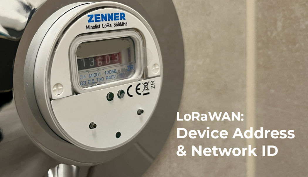
Each LoRaWAN end device has its own device address, which is either statically assigned (ABP) or assigned by the LoRaWAN network (OTTA)
read more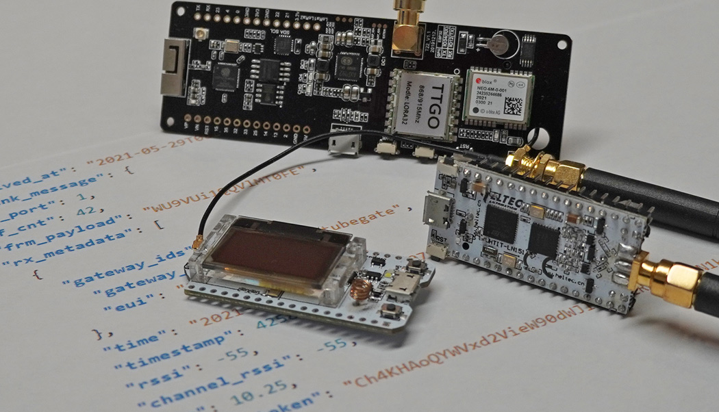
The Frame Counter (ABP) is an important security feature in the LoRaWAN network. This article is about the permanent storage of the current counter.
read more
05.03.2025
25.02.2025
25.02.2025
12.02.2025
AEQ-WEB ist ein Blog von Alex & Andi, der sich mit Elektronik, Funk & Software beschäftigt
read moreAEQ-WEB © 2015-2026 All Right Reserved