Amplifying Analog Voltages with the LM358
05.03.2025
Elektronik | Funk | Software
Der Technik-Blog
05.03.2025

25.02.2025
25.02.2025
12.02.2025

The frame counter is a security feature of LoRaWAN. While with OTTA the frame counter is reset after each JOIN, the frame counter remains in place with ABP. Especially with self-built nodes like the ESP32 LoRa Board or an Arduino Uno, there are problems with the frame counter in ABP mode. This article is about possible solutions for keeping the frame counter status in the ESP32 after a reset or power failure.
Source Code LoRaWAN ABP with active Frame Counter
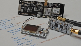
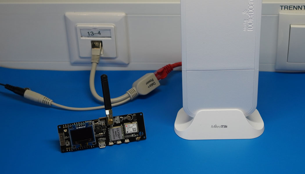
ESP32 LoRaWAN with ABP
The frame counter is a counter that is incremented by the value 1 with each transmission. The current value is stored both in the end device and on the LoRaWAN server. The uplink frame counter counts those packets that are sent from the node to the LoRaWAN network. The downlink frame counter counts those packets that are sent from the LoRaWAN network to the node. In principle, it is not possible to decrypt a data packet if you do not know the app session key. Nevertheless, it is possible to record a data packet with a receiver binary (via the modulation) and send it again. The LoRaWAN network cannot determine whether the data packet comes from the same sender or was copied from a different system and sent again. The Frame Counter prevents this. The frame counter is calculated directly into the encryption, which means that physically every data packet looks different. It is therefore not possible that a recorded data packet cannot be sent again. By the way, such an attack is also called a replay attack.
Every microcontroller and also every development board has different built-in memories. Basically, every microcontroller has a working memory (RAM) and a programm memory (usually flash). In addition, there is either a partition in the flash, where data can be stored permanently during the programme runtime, or there is an EEPROM. On many development boards you will often also find external memories such as an SPI flash or a battery-buffered RAM.
ESP32 Permanent Memory
The ESP32 has a certain memory area (usually about 20 KB) reserved in the internal flash for just such purposes.
Arduino Permanent Memory
The Arduino also has a flash memory, but this memory is usually only accessed by the boot loader. During programme runtime, access is only possible to a limited extent. But there is an integrated EEPROM, which is from 512 bytes to 2 kilobytes in size, depending on the processor type. This memory is also suitable for the frame counter. However, this article only deals with the ESP32, but memory access on the Arduino works similarly. More information about Arduino EEPROM access can be found in this article.
The following sample code shows the write and read access to the internal flash. The "Preferences Library" is used as library. This library is automatically pre-installed with the ESP32 in Arduino IDE.
//More information at: https://www.aeq-web.com

#include <Preferences.h>

Preferences preferences;

void setup() {
  delay(2000);
  Serial.begin(115200);
  Serial.println();
  Serial.print("Counter after Reboot: ");
  Serial.println(fcnt_read());
}

void loop() {
  delay(10000);
  fcnt_up();
  Serial.print("Counter: ");
  Serial.println(fcnt_read());
}

unsigned int fcnt_read() {
  preferences.begin("fcnt", true);
  unsigned int counter = preferences.getUInt("counter", 0);
  preferences.end();
  return counter;
}

void fcnt_up() {
  preferences.begin("fcnt", false);
  unsigned int counter = preferences.getUInt("counter", 0);
  preferences.putUInt("counter", counter+1);
  preferences.end();
}
In the setup, the function "fcnt_read()" calls the last frame counter and outputs it to the serial monitor. The integer function "fcnt_read" starts a memory access to the area "fcnt" with "preferences.begin". The "true" defines a read-only access. Subsequently, a new interger with the variable name "counter" is declared. The variable "counter" is read from the memory via "getUInit". The zero at the end of this line is returned if the variable was not found in the previously defined memory area. In practice, the frame counter also starts at 0 for the first time. The function returns the current counter value via the return.
The function "fcnt_up" first retrieves the current counter value from the memory (same as with "fcnt_read()"). With "putUInt" the new counter value is written into the memory. With "counter+1" the counter is increased by the value 1 before saving.
In the loop, the counter value is increased by 1 every 10 seconds with "fcnt_up". The counter value is then read from the memory and output via the serial monitor. The counter reading is thus retained even after a reset or programm upload.
Every memory has a limited number of writing cycles. Independent of whether it is the flash memory on the ESP32 or the EEPROM on the Arduino, you can expect about 100,000 writing cycles. However, it is known from practical experience that the maximum number of write cycles is significantly higher. It is not unusual for a memory error to occur for the first time after 400,000 cycles on the Arduino EEPROM, for example.
| Interval | Lifetime |
|---|---|
| Every minute | ~ 70 Days |
| Every 5 minutes | ~ 347 Days |
| Every 25 minutes | ~ 2,8 Years |
| Every Hour | ~ 11,4 Years |
In order to save the respective memory, you can also save the frame counter at certain intervals. If you have a weather station that sends new data every 10 minutes, you could also write the frame counter to the memory only every hour. If there is a power failure and the counter reading is not stored synchronously with the LoRaWAN network, it is to be expected that the next data packets will be rejected. As soon as the counter is again higher than that of the previous valid data packet, the LoRaWAN network accepts these data packets again. So you can save the memory lifetime, but you have to accept short downtimes after a power failure of the hardware. The only alternative is to switch to OTTA.
The complete source code is based on the LMIC Library with adapted sample code for the permanent storage of the frame counter. The full sample code and all other examples are on this page.

The UDP packet forwarder developed by Semtech handles the data transmission of the received packets from the LoRaWAN gateway to the network server
read more
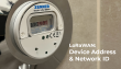
The Frame Counter (ABP) is an important security feature in the LoRaWAN network. This article is about the permanent storage of the current counter.
read more
05.03.2025
25.02.2025
25.02.2025
12.02.2025
AEQ-WEB ist ein Blog von Alex & Andi, der sich mit Elektronik, Funk & Software beschäftigt
read moreAEQ-WEB © 2015-2026 All Right Reserved