Amplifying Analog Voltages with the LM358
05.03.2025
Elektronik | Funk | Software
Der Technik-Blog


05.03.2025

25.02.2025
25.02.2025

12.02.2025
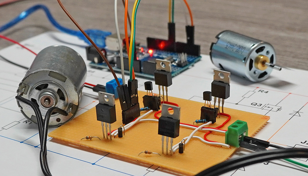
The H-bridge or also called 4-quadrant operation is an interconnection of MOSFETs for controlling DC motors. By driving specific MOSFETs, this can reverse the polarity of a DC motor and thus determine the direction of rotation. In addition, this circuit can also be used to brake the motor. Controlling the speed with PWM is also possible. This article is about the construction of an H-bridge with MOSFETs for operation with microcontrollers like Arduino, ESP32, STM & Co.
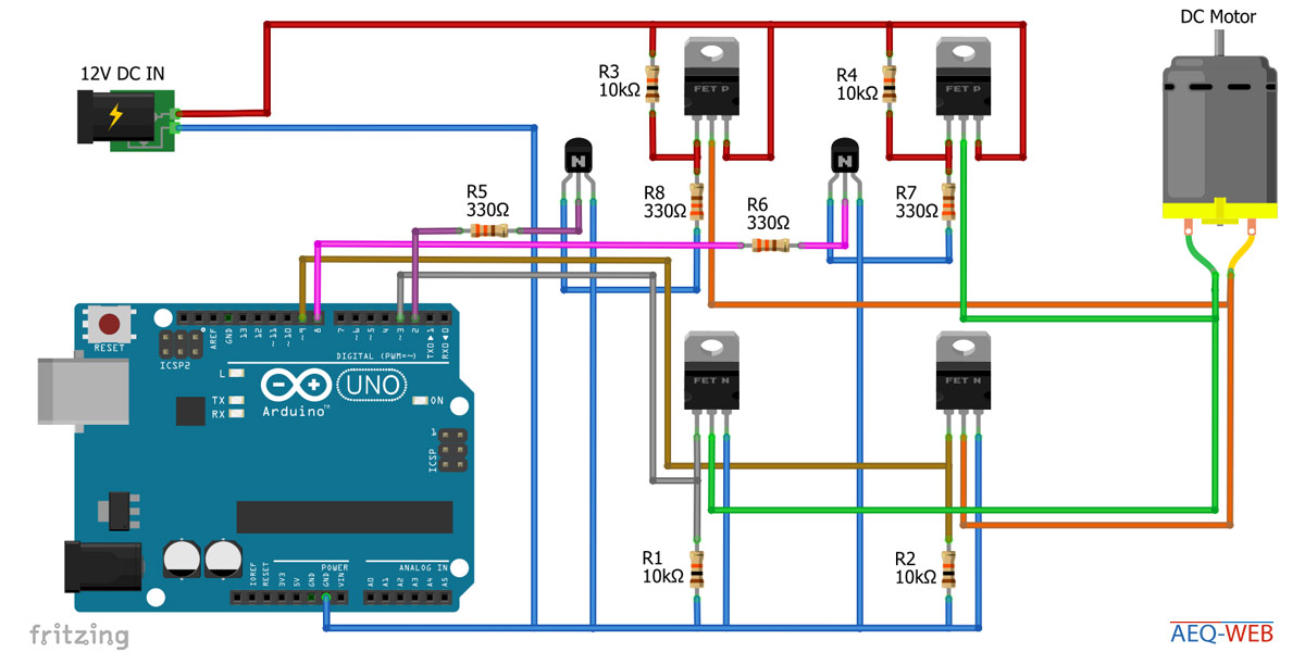
Four MOSFETs are used as power semiconductors. Two of them are IRL N-channel MOSFETs (logic level MOSFET) and the other two are conventional IRF P-channel MOSFETs. In addition, two NPN transistors are needed to drive the P-channel MOSFETs. Furthermore, some resistors and four diodes are needed.
Attention: Commercial N-channel MOSFETs (IRF) cannot be used for this circuit, because they need a gate voltage of 10 volts. Logic level MOSFETs switch fully from 5 or 3.3 volts and can be connected directly to the I/O pin. P-channel MOSFETs are not affected by this, because they are switched anyway via the transistors with a voltage difference of at least 10 volts. More information can be found in the following article: MOSFETs und Mikrocontroller (German)
The H-bridge consists of a total of four switches (MOSFETs in further sequence). Depending on the switch position, the motor can be set to counterclockwise or clockwise rotation. The following graphic shows a simplified representation of the H-bridge.
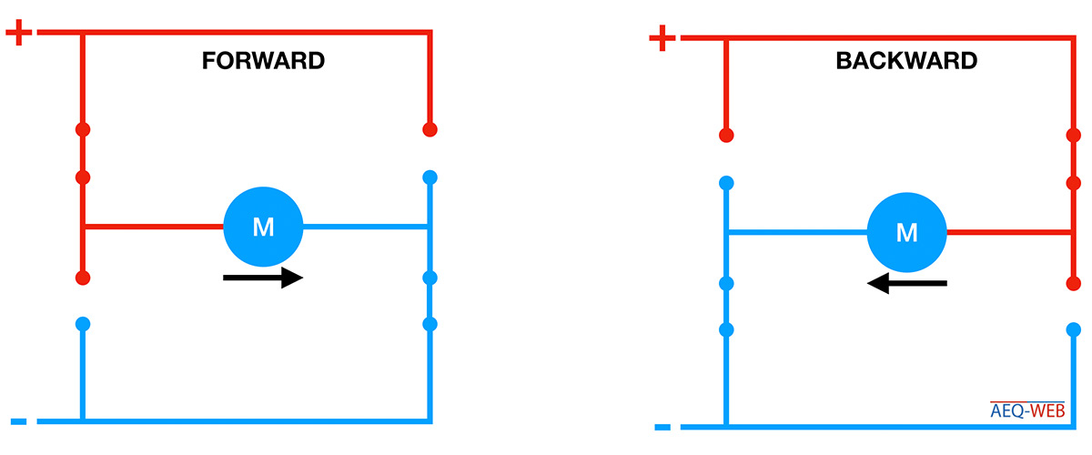
In forward running, S1 and S4 are activated. The power supply now runs from the positive pole via S1 to the motor and continues after the motor via S4 to the negative pole. S2 and S3 must be open!
In return S2 and S3 are activated. The power supply now runs from the positive pole via S2 to the motor and continues after the motor via S3 to the negative pole. S1 and S4 must be open!
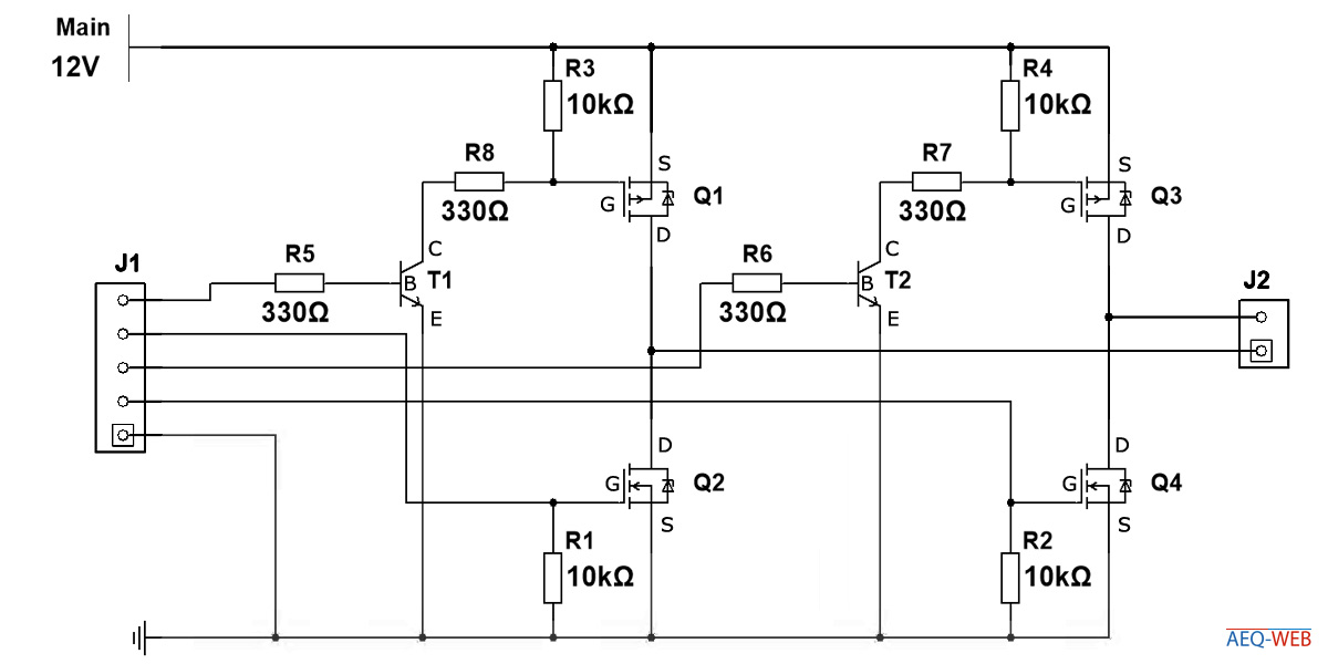
The resistors R5 and R6 are classic series resistors for the NPN transistors. The NPN transistors (T1, T2) are used to control the P-channel MOSFETs (Q1, Q3). If a positive voltage is applied to the base of the respective NPN transistor, it switches on. This process creates a negative potential at the gate of the P-channel MOSFET, which triggers the P-channel MOSFET to switch on. Again, series resistors (R7, R8) for current limitation are located between transistor and MOSFET. As soon as the voltage at T1 or T2 drops, these resistors will block and the respective P-channel MOSFET will switch off. For the shutdown to work quickly and correctly, a pull-up resistor (R3, R4) is needed. These resistors are quite high impedance, so only a small current can flow. If the transistors are switched off, the supply voltage (+12V) is applied to the gate of the respective P-channel MOSFET. This puts the MOSFET into a blocking state.
The N-channel MOSFETs (Q2, Q4) can be connected directly to the digital output of the microcontroller. These are IRL MOSFETs, which switch fully through at 3.3 or 5 volts depending on the type. A series resistor is not necessary here. The resistors R1 & R2 are also level pullers (PullDown). As soon as the digital output switches to low, the resistors (R1, R2) push the level down and ground is applied to the gate, which puts the MOSFET back into a blocking state.
The diodes (D1 to D4) are freewheeling diodes, which are necessary for operation with inductive loads.
The following is a simplified circuit diagram with the Arduino without connected protection diodes:
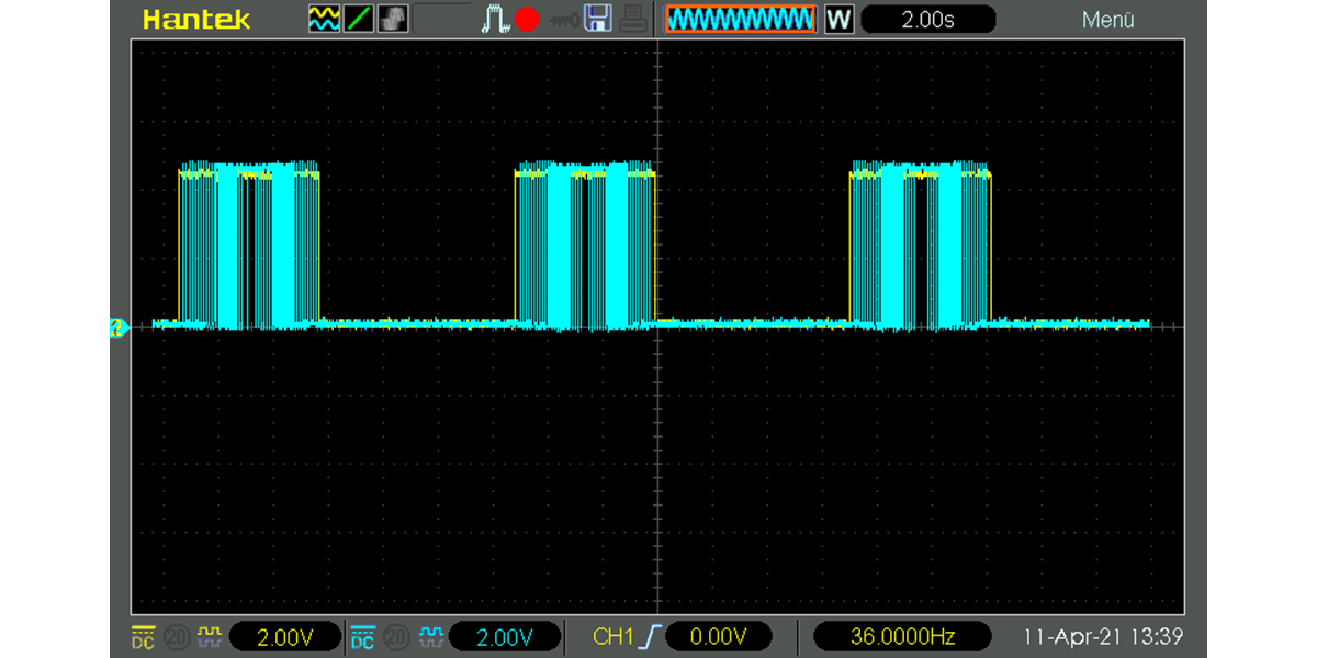
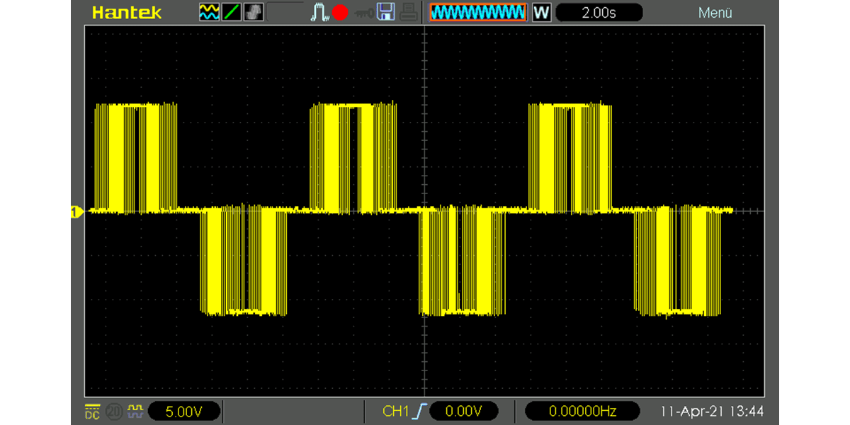
It is possible to control the speed of a connected motor with PWM (pulse width modulation). Basically you should avoid a parallel connection of two acting MOSFETs in this H-Bridge. First the P-channel MOSFET is activated and thus the positive pole is switched through to the motor. Then PWM is used to temporarily switch through the negative pole, which causes the motor to start. PWM can also be generated in reverse via the P-channel MOSFET, but this can cause problems, especially with high PWM. In addition, the upstream NPN transistor is often not suitable for extremely fast circuits. The following screenshot shows how first the P-channel MOSFET (yellow) is switched on and then a PWM is generated via the N-channel MOSFET (blue). After the N-channel MOSFET is permanently switched off again, the P-channel MOSFET also switches off again:
The sample code slowly starts a DC motor with PWM. The motor then remains continuously switched on for about two seconds and is then slowly switched off again with PWM. After that, the polarity is reversed and the motor is started up again with PWM. This process continues in an endless loop.
//More Information at https://www.aeq-web.com/

int P_FET_Q1 = 2;
int N_FET_Q4 = 3;

int P_FET_Q3 = 8;
int N_FET_Q2 = 9;

int PWM = 0;

void setup() {
  pinMode(P_FET_Q1, OUTPUT);
  pinMode(N_FET_Q2, OUTPUT);
  pinMode(P_FET_Q3, OUTPUT);
  pinMode(N_FET_Q4, OUTPUT);
}

void loop() {

  digitalWrite(P_FET_Q1, HIGH);
  delay(10);
  //Drive Forward (0% -> 99%)
  while (PWM < 255) {
    analogWrite(N_FET_Q4, PWM);
    PWM++;
    delay(10);
  }
  //Drive Forward (99% -> 0%)
  while (PWM > 0) {
    analogWrite(N_FET_Q4, PWM);
    PWM--;
    delay(10);
  }

  PWM = 0;

  digitalWrite(N_FET_Q4, LOW);
  digitalWrite(P_FET_Q1, LOW);

  delay(1000);

  digitalWrite(P_FET_Q3, HIGH);
  delay(10);
  //Drive Backward (0% -> 99%)
  while (PWM < 255) {
    analogWrite(N_FET_Q2, PWM);
    PWM++;
    delay(10);
  }
  //Drive Backward (99% -> 0%)
  while (PWM > 0) {
    analogWrite(N_FET_Q2, PWM);
    PWM--;
    delay(10);
  }

  PWM = 0;

  digitalWrite(N_FET_Q2, LOW);
  digitalWrite(P_FET_Q3, LOW);

  delay(1000);

}
The following screenshot shows the final output voltage (with connected load resistor ~2.5 A), which is generated by circuit and software:
The components used for the test setup can be found in the following tables:
| Part | Value |
|---|---|
| R1, R2, R3, R4 | 10 K |
| R5, R6, R7, R8 | 330 Ohm |
| T1, T2 | BC547 |
| D1, D2 | 1N4007 |

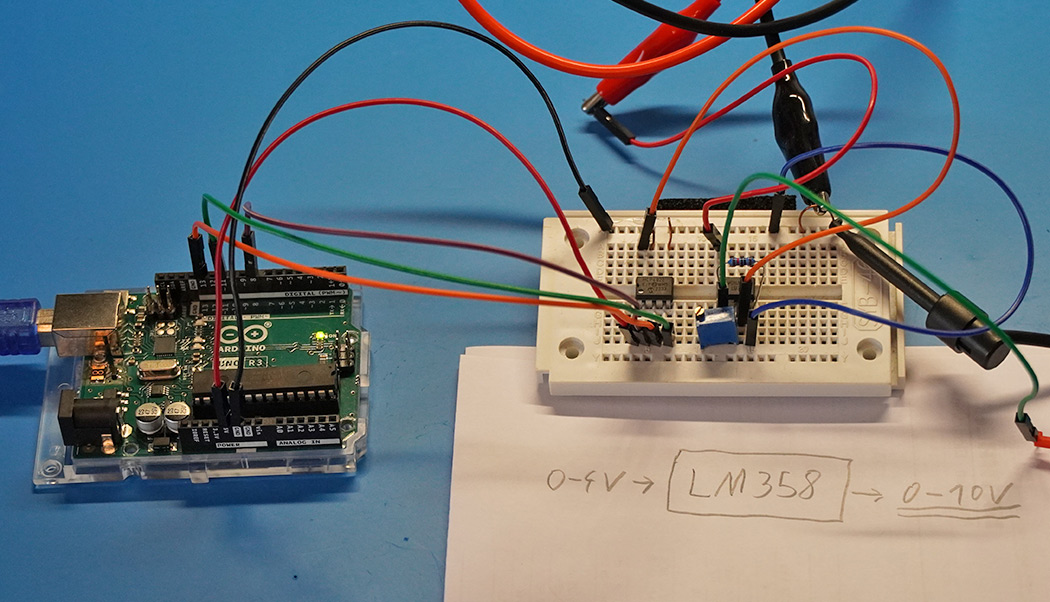
The last article was about generating an analog voltage with the Arduino. The generated 0-4V can be amplified to 0-10V using the LM358 operational amplifier.
read more
Control direction and speed of a DC-Motor with MOFETs on an Arduino. Four-quadrant operation
read more
05.03.2025
25.02.2025
25.02.2025
12.02.2025
AEQ-WEB ist ein Blog von Alex & Andi, der sich mit Elektronik, Funk & Software beschäftigt
read moreAEQ-WEB © 2015-2026 All Right Reserved