Amplifying Analog Voltages with the LM358
05.03.2025
Elektronik | Funk | Software
Der Technik-Blog
05.03.2025

25.02.2025
25.02.2025
12.02.2025
There is also a video on YouTube for this article: Arduino Current Power Sensor - Measure current and power in an AC circuit
In this article, we test about a very cheap inductive AC power meter. Unfortunately, there is no information from the manufacturer how the component works or how accurate the measurement is. In this article we write about our test and the accuracy of this sensor. In addition, we show how the sensor works with an Arduino.
The electrical structure of these inductive power meters is actually very simple and has been used by energy suppliers for decades, above all in the area of high voltage. A big advantage is that with this method high currents can be measured "without contact". The conductor or phase in the AC power grid is passed through this component. When a consumer is connected, a current flows through the line which builds up a magnetic field around the line. Due to this magnetic field, a small voltage is induced in a coil which is located in this component. When more current flows, the induced voltage in the coil is higher. A microcontroller can read the analog voltage, and can convert the input voltage into the flowing current. If you multiply current with the voltage, the power can be calculated in watts.
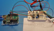
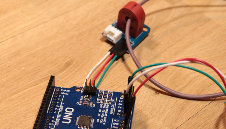
For the calculation of power consumption we use an Arduino Uno board. The whole project can also be realized very easily with an ESP32 or NodeMCU. For the calculation, only one analog input on the microcontroller is needed. The input voltage value is then be converted into current and power. In addition, the sensor is still connected to 5 volts and to the ground of the microcontroller.

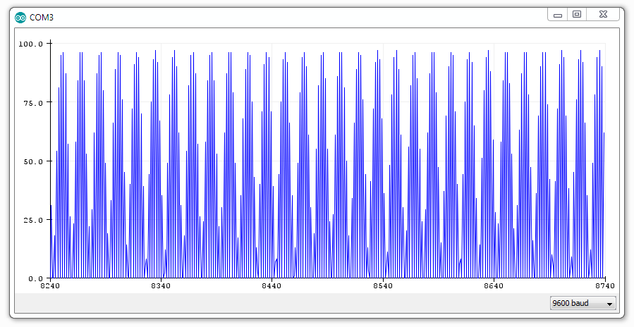
A big problem is the correct measurement at AC voltages. The AC grid in Europe has 50 Hz, which means that there are 50 oscillations per second on the measured line. If the analogue input is read out quickly, then you can see that the voltage varies a lot, but very evenly. The following graphic from the Serial Plotter shows the oscillations of the AC power grid. In order to obtain a relatively constant value, the measurement has to run over a certain period of time and from this the mean value must be calculated.
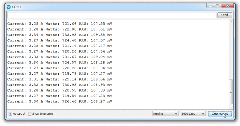
The software displays the determined current in the serial monitor and also calculates the power in watts. The measurement is made 2000 times in succession, which then calculates a mean value. This value barely fluctuated in our attempt. Subsequently, the analog value is multiplied by 7. This ensures that you have a real measure. An example: At the analogue input, we get the value 60. At present, 4.2 amperes of current are measured at the load. The output in the Serial Monitor should be 4.20 amps. With a formula ((60 * 7)/100) this value is reached. Thus you get the fixed current value as float-integer.
For the sensor to work properly, it must be balanced with a current meter or a power meter. The voltage at the analog input is not always the same, which is why the formula in the code must necessarily be compared with a reference device.
The sensor works very reliable, but is not linear! This means that the sensor delivers an exact result only within a certain range. In our experiment, the sensor had a maximum deviation of 12 watts between 200 and 1500 watts. At under 200 watts or over 1500 watts, the tolerance was much greater. For a consumer consuming exactly 50 watts, the sensor used a consumption of 80 watts, which is clearly above any tolerance limit. It is basically possible to work around this problem with mathematical formulas, but there is a lot of effort behind it to properly calibrate the sensor. In summary, we believe that the sensor works quite well for small projects, but is not suitable for accurate metering or energy billing.
With the sensor it is also possible to measure a three-phase network. This requires three sensors, each of which passes through one phase. The individual partial flows must then be added together to determine the total power consumption. On the Arduino board, the sensors are connected to the analog pins from A0 to A2.

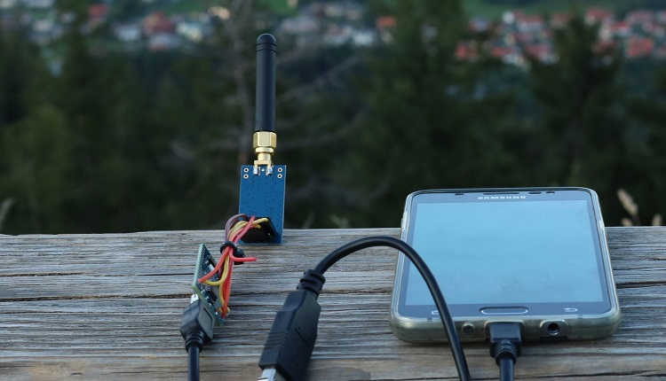
On this page we will show you how to make a data transfer with the CC1101 and an Arduino. Wiring plan and libraries are available on AEQ-WEB
read more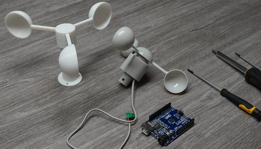
With a microcontroller like the Arduino, a small circuit and appropriate software the wind speed can be measured with an anemometer
read more
05.03.2025
25.02.2025
25.02.2025
12.02.2025
AEQ-WEB ist ein Blog von Alex & Andi, der sich mit Elektronik, Funk & Software beschäftigt
read moreAEQ-WEB © 2015-2026 All Right Reserved